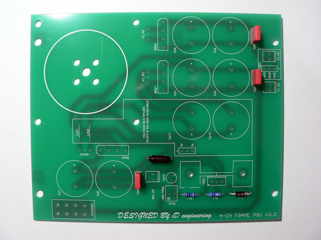
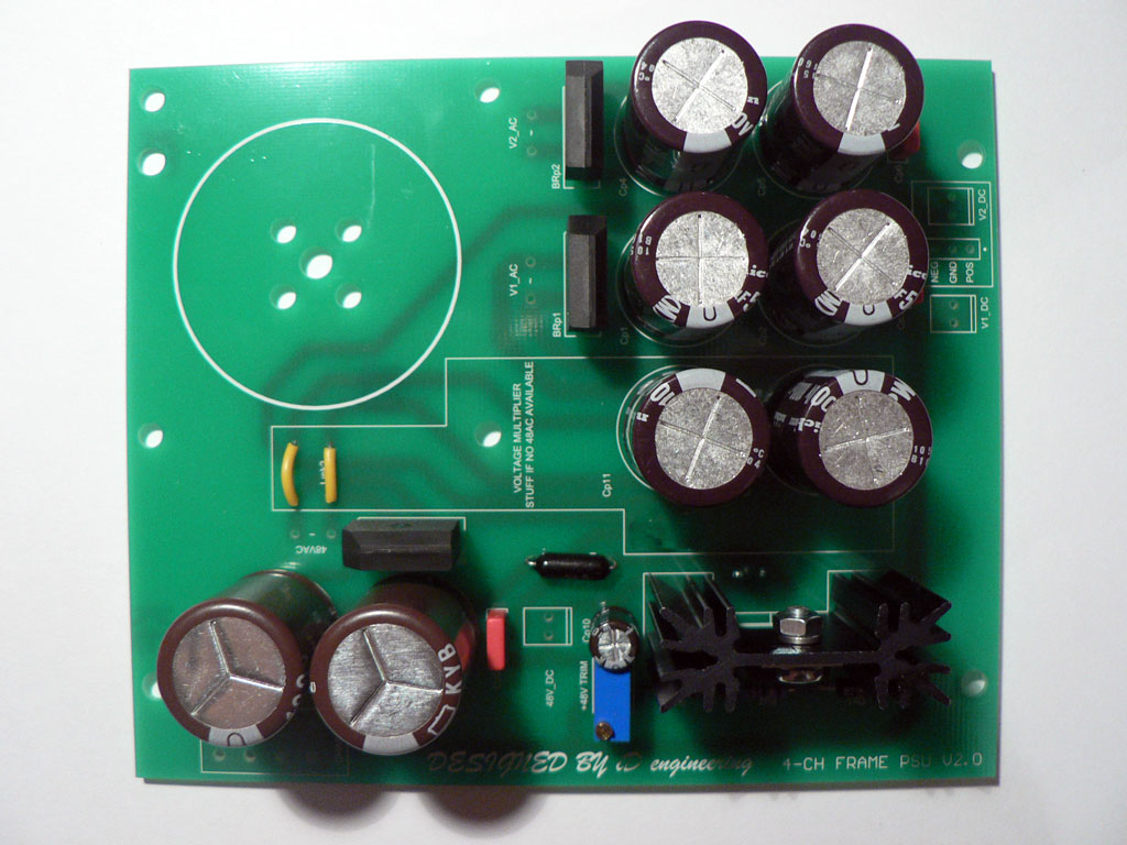
| Solder all resistors |
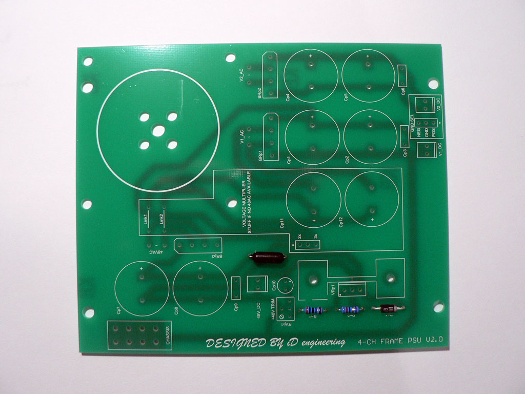 |
| Solder all film capacitors |
 |
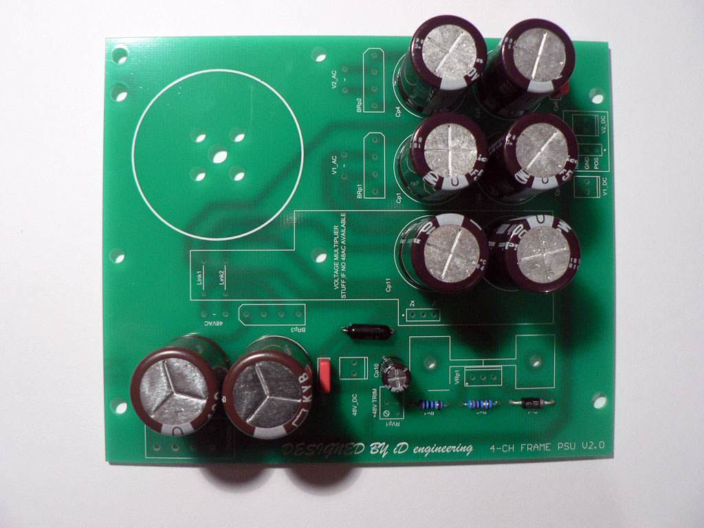
| Solder all electrolytic capacitors and trimmer resistor. Don't solder Cp11 and Cp12 if you have a transformer with dedicated 48V winding. |
 |
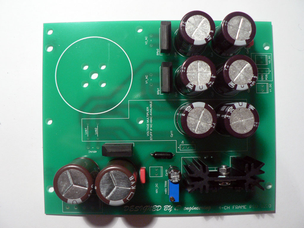
| Solder all diode bridges (observe polarity!) and voltage regulator. Make sure to mount the voltage regulator to the heatsink first and solder to the PCB after that. Otherwise you may stress a component and potentialy damage it. Solder the heatsink to the PCB as well. |
 |
|
Finally install the voltage doubler links (Link1 and Link2). IMPORTANT! If you have a transformer with dedicated 48V winding, you should NOT install these links. In this case the section marked "VOLTAGE MULTIPLIER" should be left unpopulated. Use any of the CHASSIS pads to connect PSU ground to chassis star ground point. There are three options for mounting the power transformer:
|
 |
|
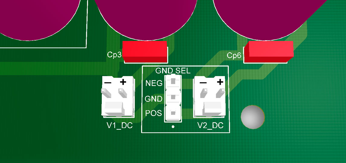
You can see the output polarity on the picture. V1 output is always referenced to ground/chassis and thus is always positive. V2 output is floating and can be made either positive or negative. In order to get dual rail +/- output connect pins 1 and 2 ("GND" and "POS") of GND SEL header. In order to get two positive rails connect pins 2 and 3 ("GND" and NEG") of GND SEL header. |
 |
|
Testing procedure:
|