|
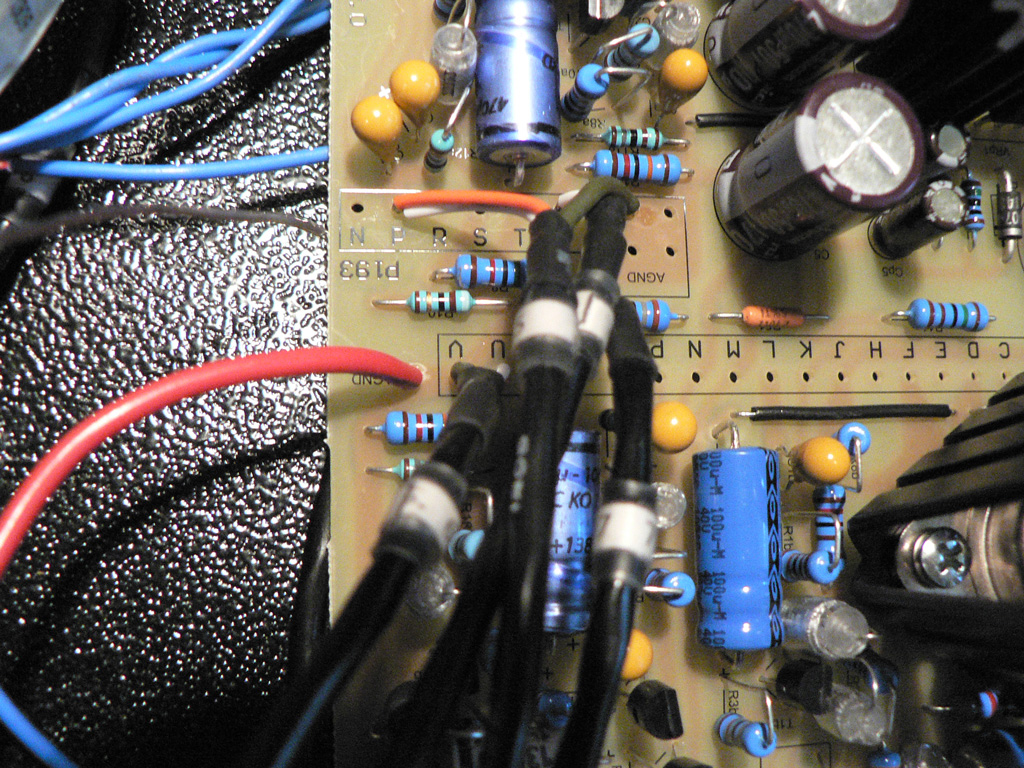
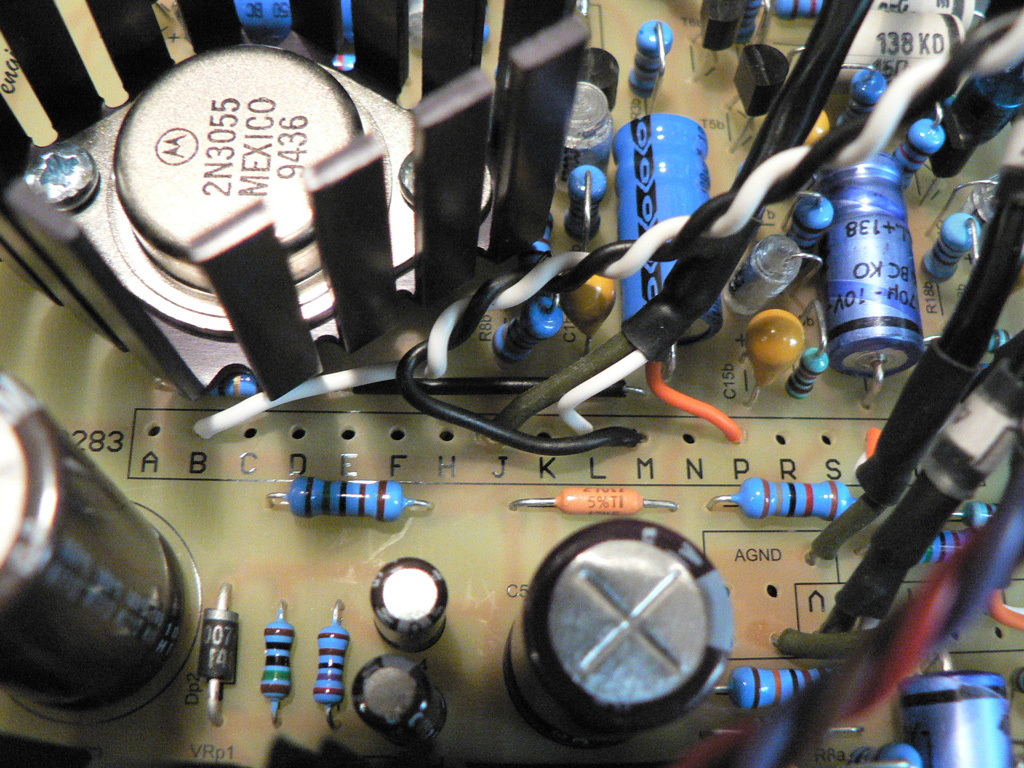
Solder the ground wire from the Gain switch PCB to the "AGND" pad near the P283. |
 |
|
Solder output trim wire to the pads "P" (CW), "L" (wiper) and "J" (CCW) of the P283. |
 |
|
Solder the opposite end of the output trim wire to the potentiometer on the front panel. |
 |
|
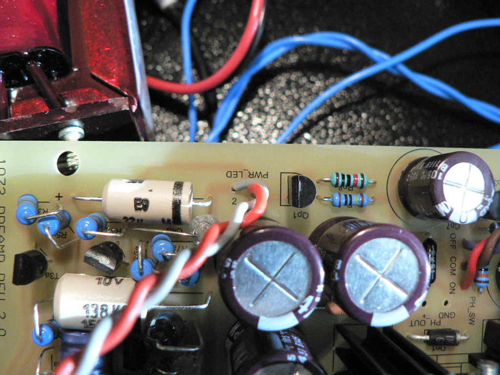
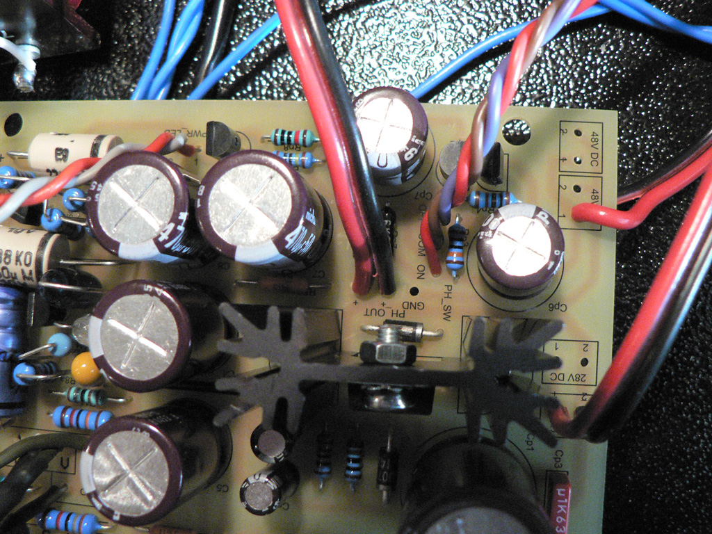
Solder wires from the power LED to the "PWR_LED" pads on the PCB. |
 |
|
Solder phantom power wires from the input XLR to the "PH_OUT" pads marked with "+". Order doesn't matter here.
Solder three pieces of 25cm (9.8") wire to the "PH_SW" pads on the PCB. |
 |
|
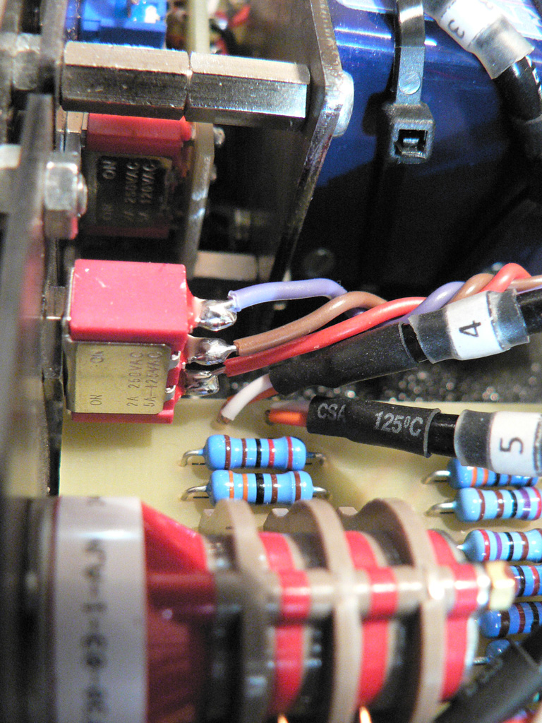
Solder two opposite ends of wires to the Phantom switch:
|
 |
|
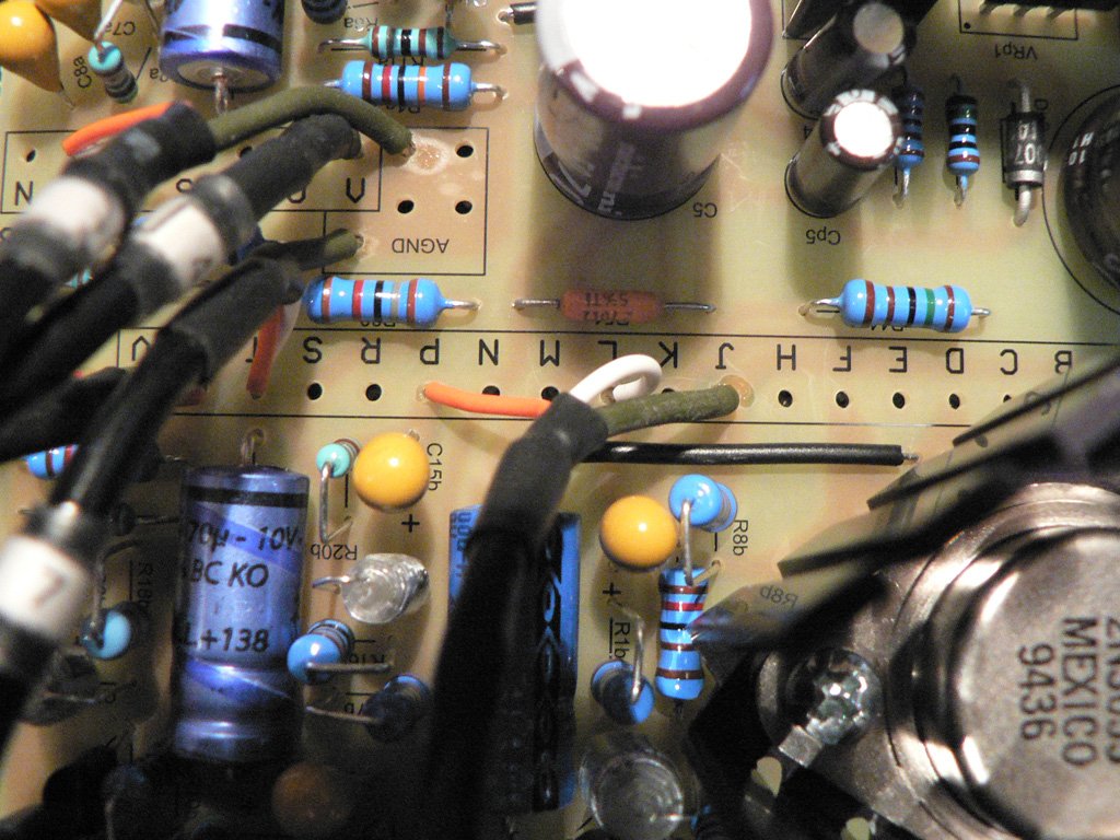
Solder two pieces of 20cm (7.8") twisted wires to the pads "B" and "M" of the P283. |
 |
|
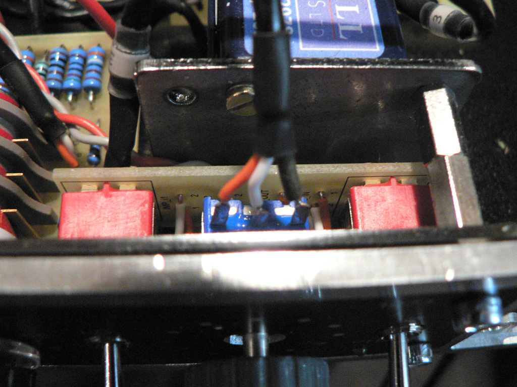
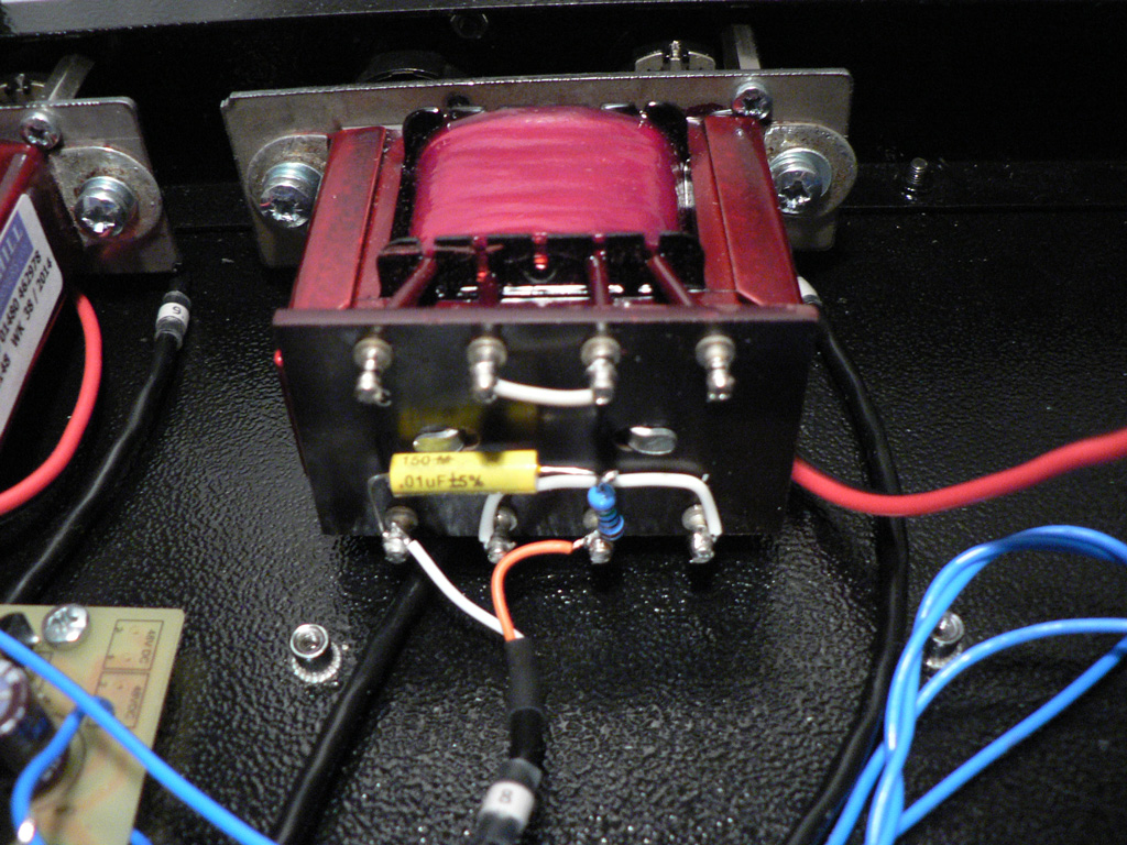
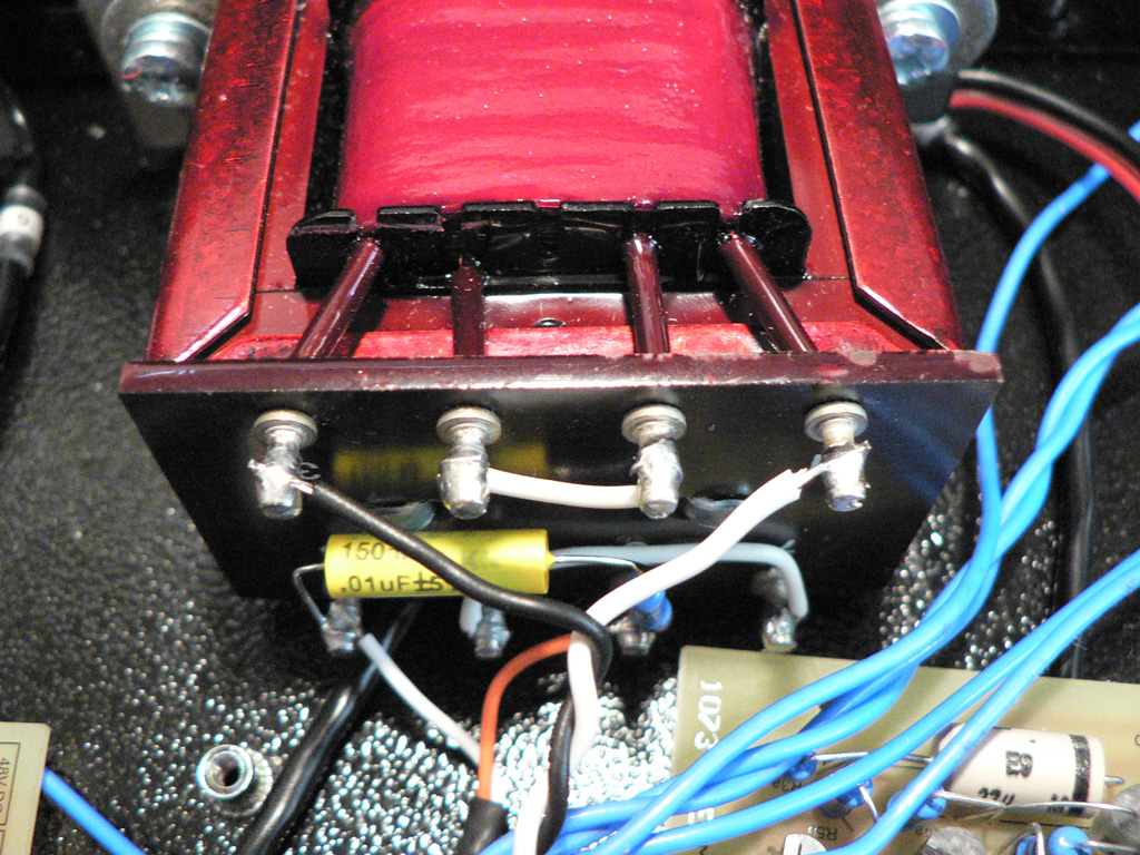
Fix the output transformer on the mounting bracket to the XLRs mounting holes.
Solder the wire "8" to the pins "5" (hot) and "8" (cold) of the transformer. |
 |
|
Solder the wire from the pad "B" to the pin "1" of the transformer.
Solder the wire from the pad "M" to the pin "3" of the transformer. |
 |
Let's move on to the Wiring - power and ground