|
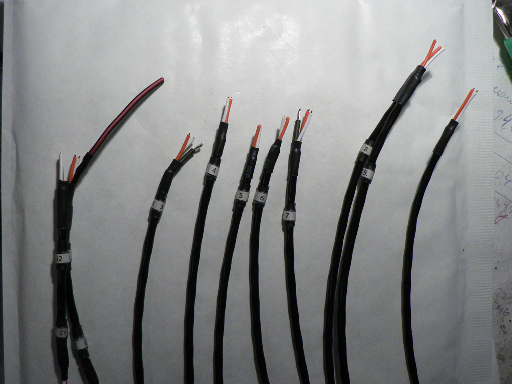
Let's prepare the signal wires. All wires are marked according to the edited schematic of the 1073.
Most wires have the shield exposed at one end only. Exceptions are wires "3", "9" and output trim. They have shield exposed at both ends.
Here you can see one end of the wires. |
 |
|
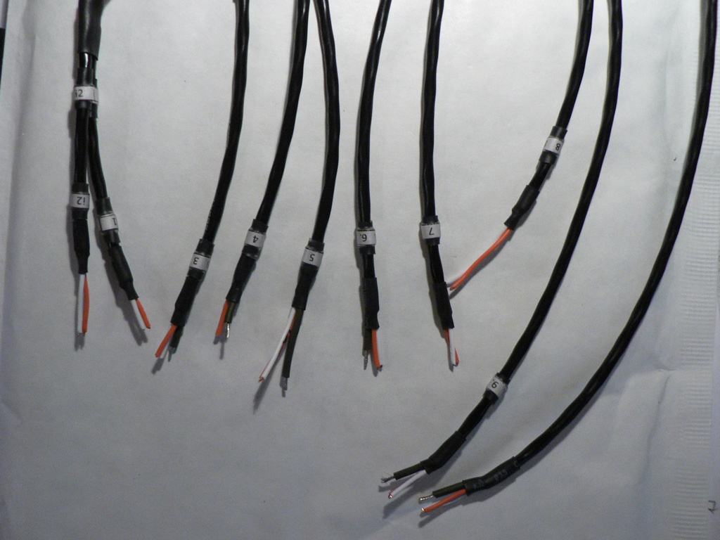
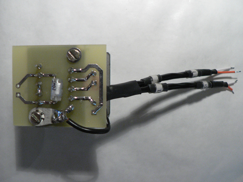
Here's the opposite end of the wires.
Wires lengths are:
|
 |
|
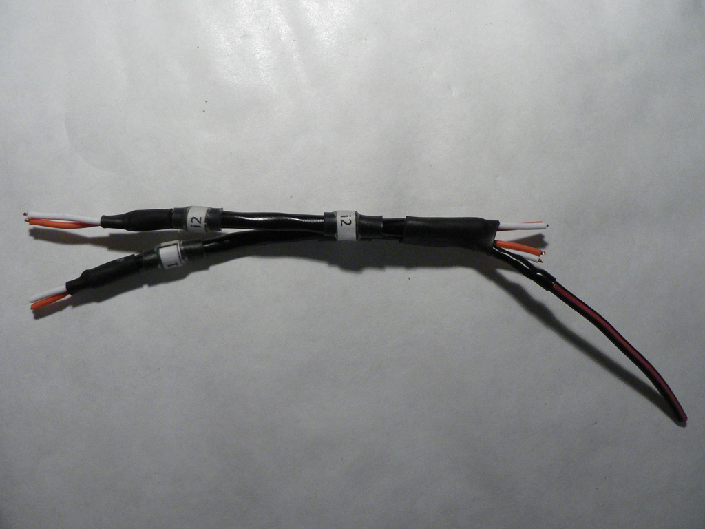
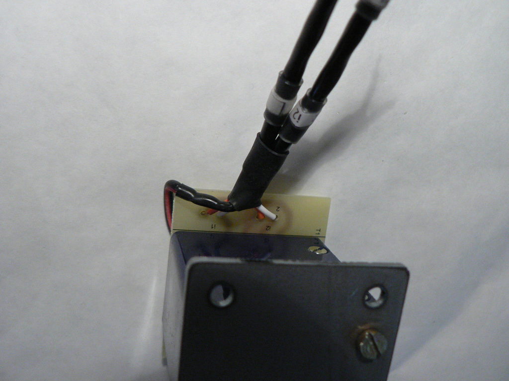
Here you can see the details of i1/i2 wires connection.
Remove the shield at one end of both wires. Connect shields of both wires together at the opposite end. Solder a piece of insulated wire to this joint.
Put heatshrink tubing around all exposed conductors. |
 |
|
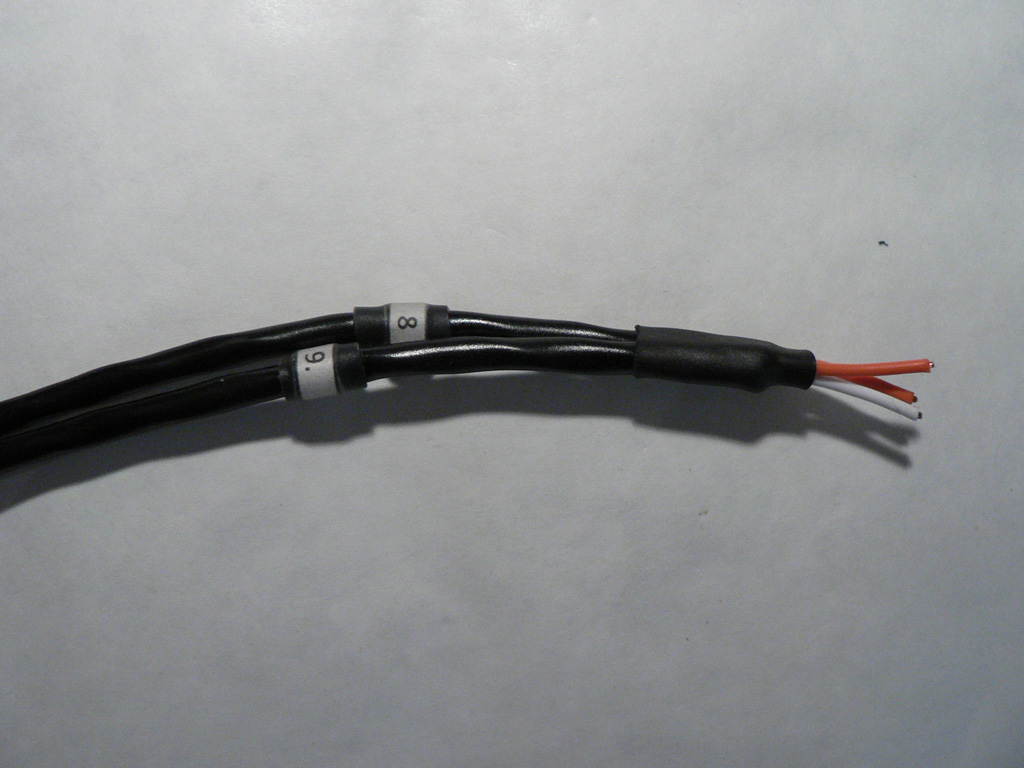
Here are the details of wires "8" and "9".
Wire "8" has the shield exposed at one end. Wire "9" has the shield exposed at both ends. Connect both shields together at the opposite end. You don't need further access to the shields.
Put heatshrink tubing around the shields joint. |
 |
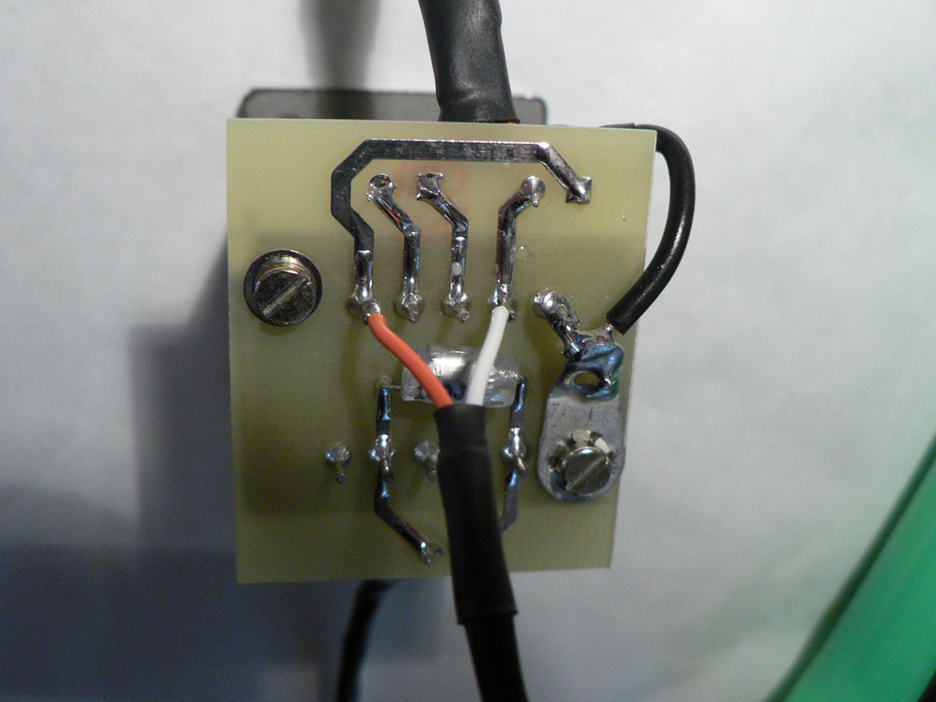
| Solder "i1"/"i2" wires to the "i1" and "i2" pads of the input transformer PCB as shown on the photo. |
 |
| Solder the shield wire to the grounding lug. |
 |
|
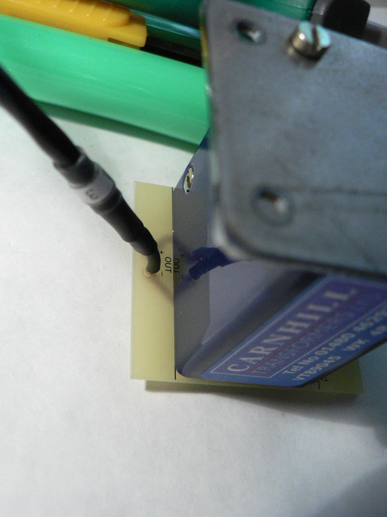
Solder the wire "3" to the "Out" pads of the input transformer PCB. Please note that both hot and cold conductors are joined together and soldered to the "+" pad, the shield is soldered to the "-" pad. |
 |
|
Solder the mic input wire (the end with the shield isolated) to the pins 2 (hot) and 5 (cold) of the input transformer as shown. |
 |
|
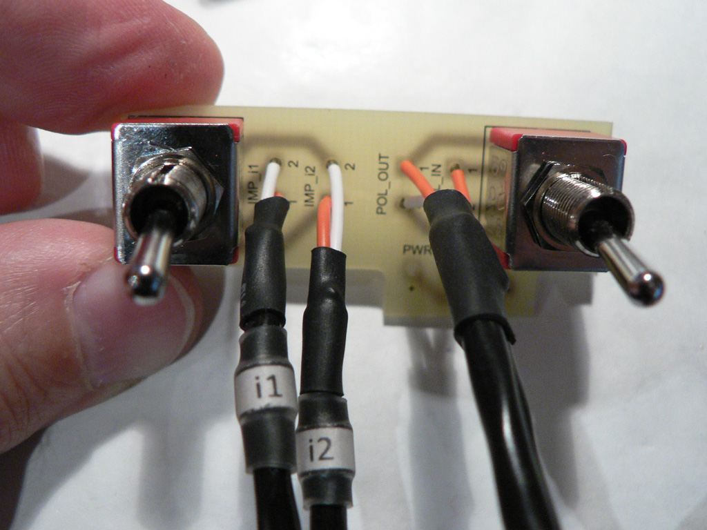
Solder other ends of "i1" and "i2" wires to the pads "IMP_i1" and "IMP_i2" of the switches PCB.
Solder the joint end of wires "8" and "9" to the following pads:
|
 |
Let's move on to the Wiring - part 2