There are four PCBs in the 1290 mic preamp module: input transformer PCB, gain switch PCB, Impedance and Phase switches PCB and main PCB.
|
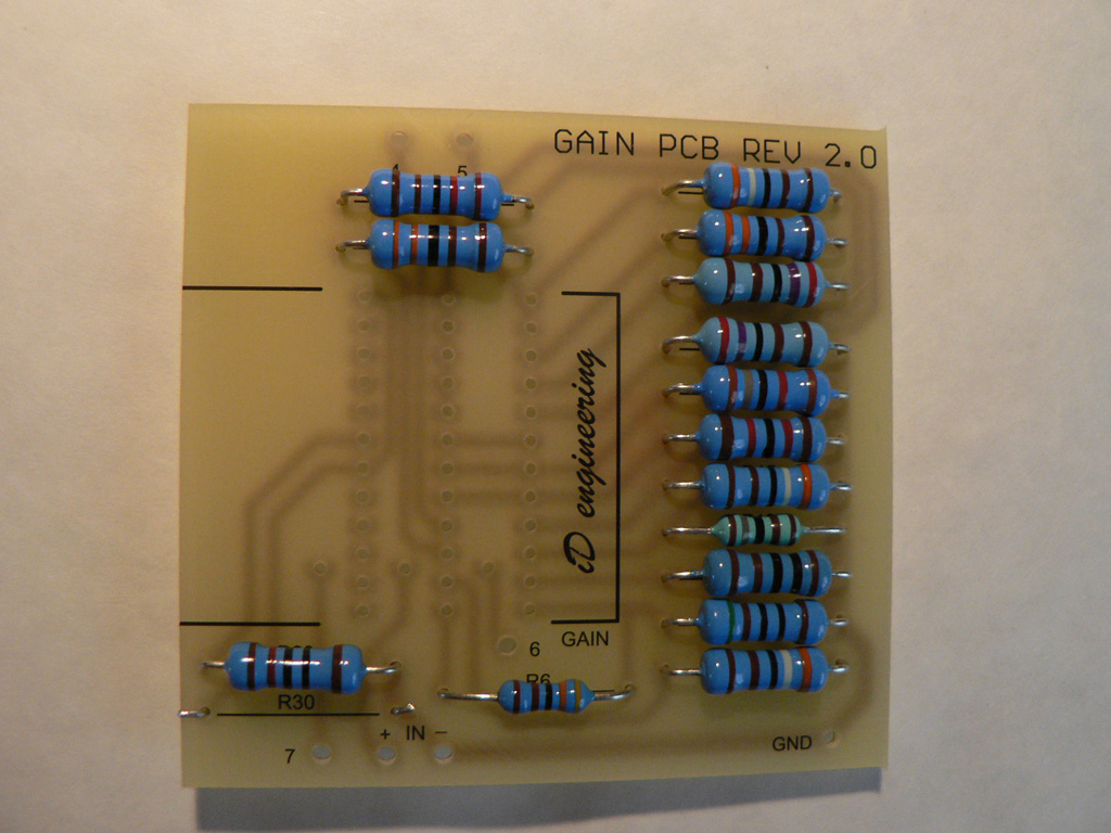
Let's start with the Gain swicth PCB.
Solder all resistors except R30. Designators are taken from the edited version of the 1073 circuit. |
 |
|
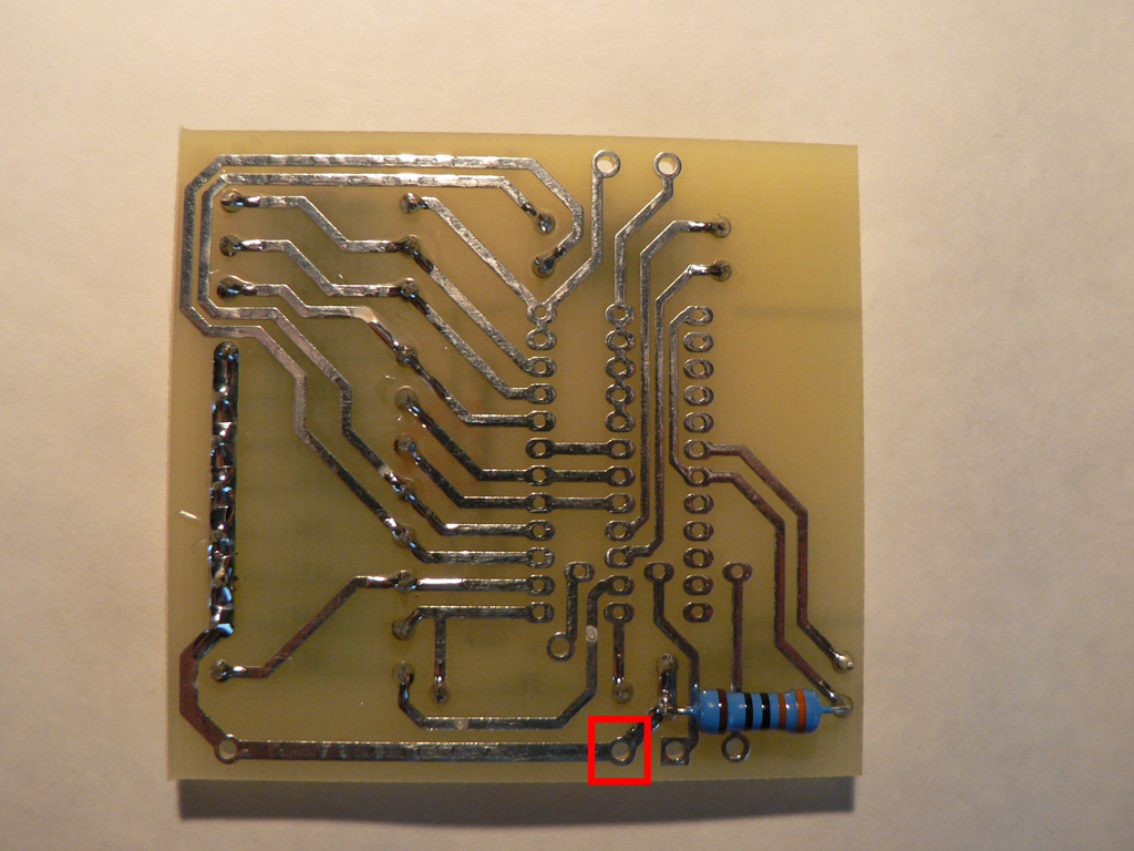
Solder R30 to the opposite side of the PCB.
Wire that goes to pad "7" (marked with red) should be connected at this side of the PCB as well. We'll do it later though. |
 |
|
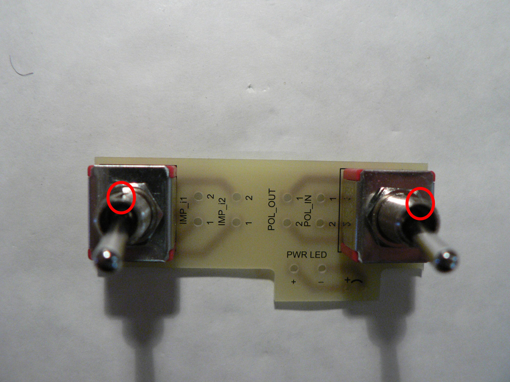
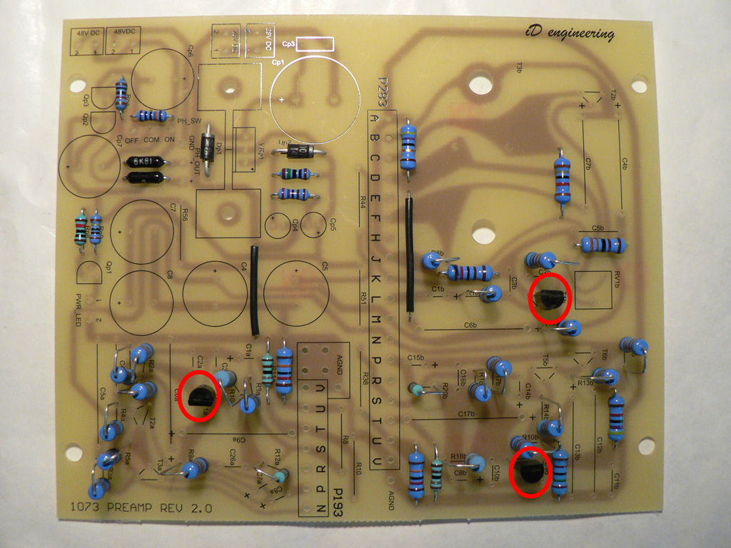
Solder two DPDT switches to the PCB. Make sure that the recesses on the bushings are oriented as shown on the photo (circled with red). |
 |
|
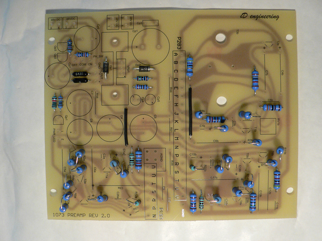
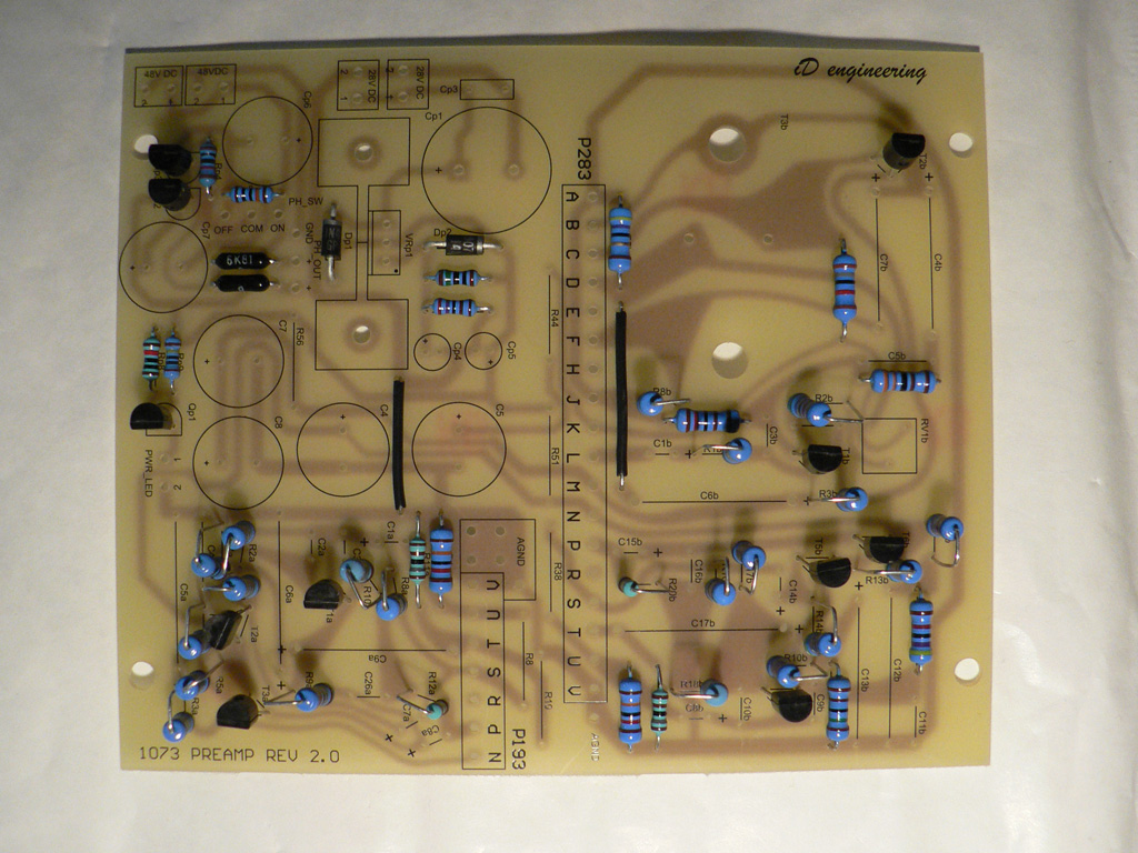
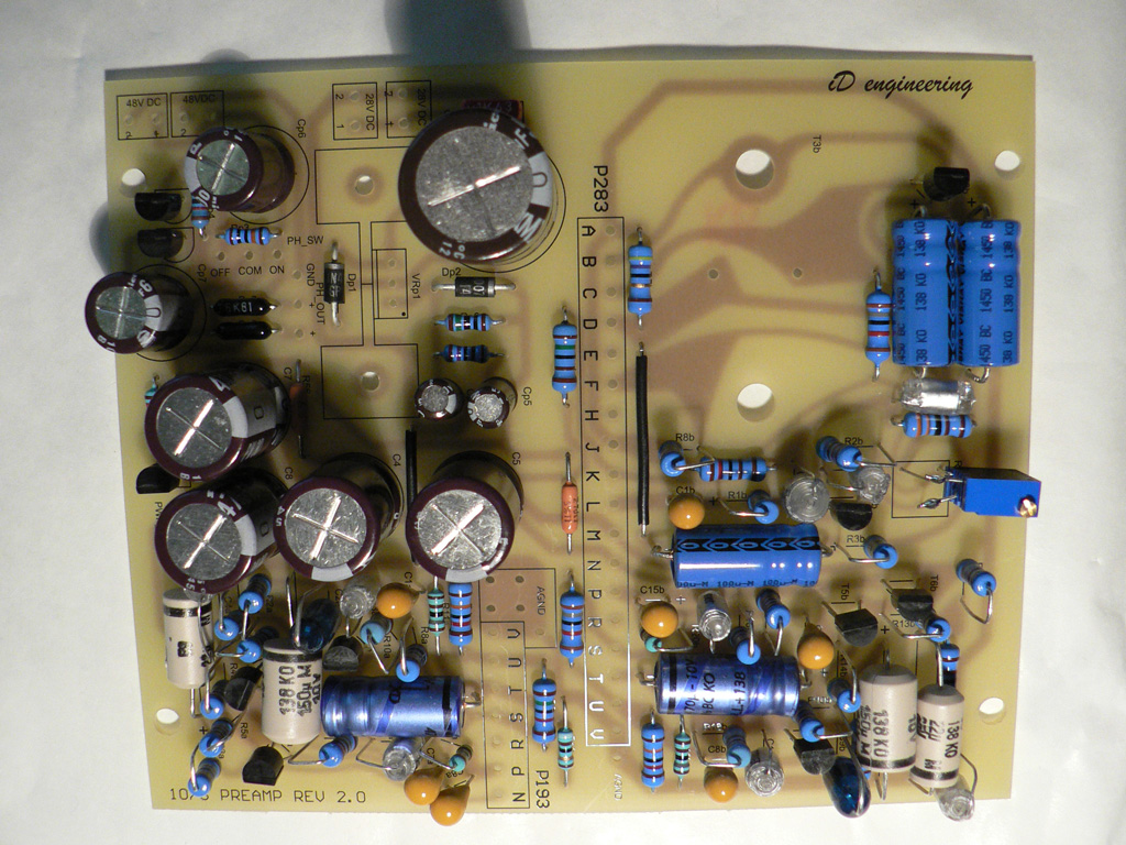
Solder wire links, resistors and diodes to the main PCB. |
 |
| Solder three transistors with hfe>600 (T1a, T1b, T4b) |
 |
| Solder the remaining transistors. |
 |
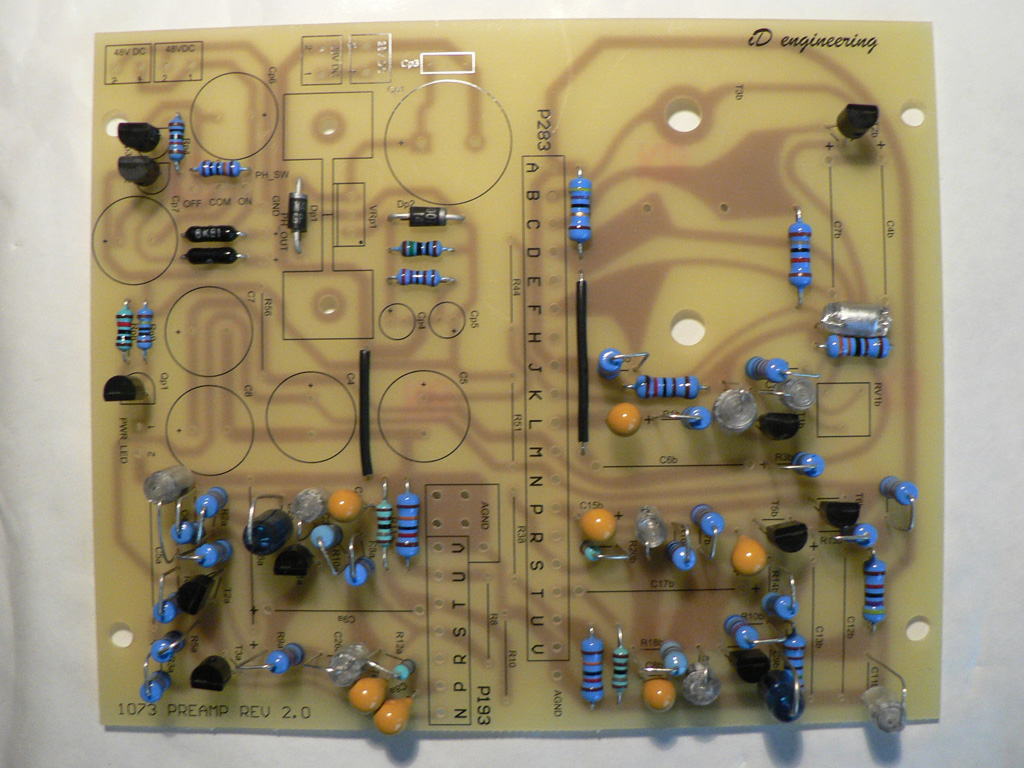
| Solder all film and tantalum capacitors. |
 |
|
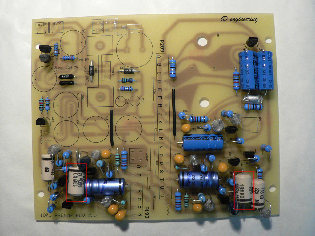
Solder all axial electrolytic capacitors.
Pay attention to the capacitors marked with red rectangle (C6a, C13b). They are placed above the other components.
It's quite a tight fit. Make sure that there are no shorts between the component leads. If in doubt, isolate them. |
 |
| Solder all radial electrolytic capacitors. |
 |
|
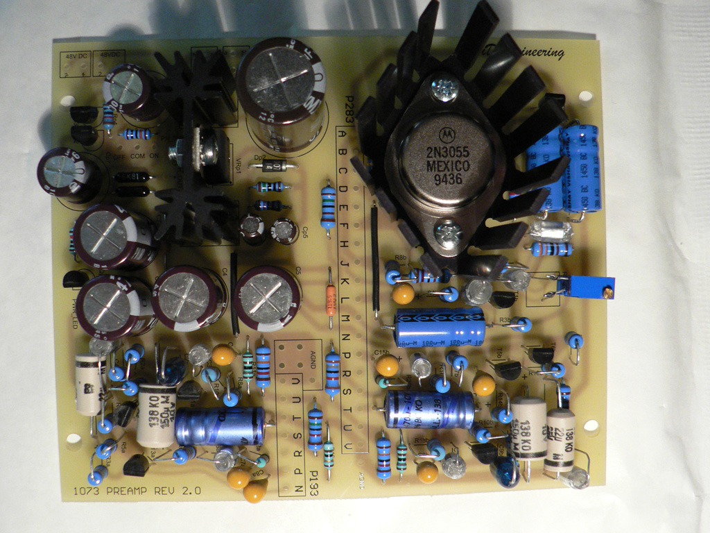
Mount voltage regulator on the heatsink and sloder them to the PCB (do NOT mount the regulator to the heatsink after soldering - this will put stress on both the chip and solder joints).
TO-3 heatsink is mounted on the 5mm standoffs. Use washers and lock washers on the bottom side of the PCB to ensure good electric contact between the transistor housing and PCB trace. |
 |
|
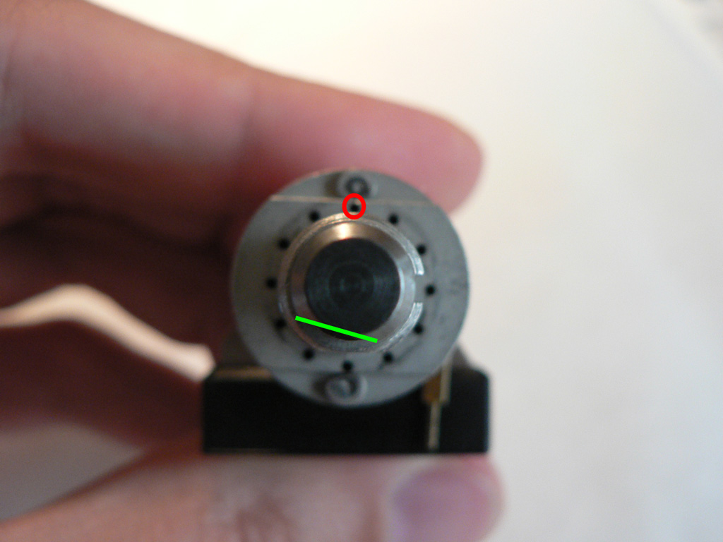
Finally, lets prepare the gain switch.
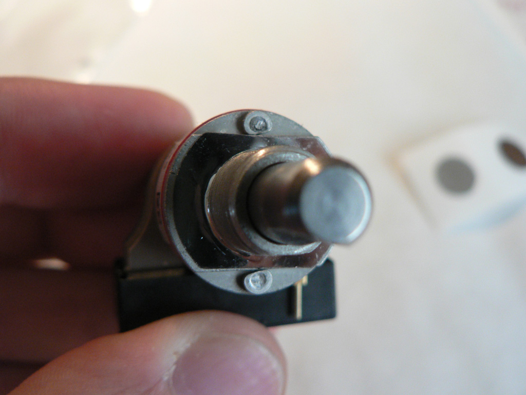
Make sure the flat is oriented as shown on the photo. Normally all switches ship in this position, but it's always a good idea to double check this.
Insert the stop pin into the hole circled with red. |
 |
|
Cover the holes with the silver adhesive foil.
Solder the switch to the gain switch PCB. |
 |
PCBs are ready. We can move on to the Transformers Preparation