|
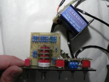
Fix the controls and PCBs to the mounting bracket as shown. Insert the LED, but don't solder it yet.
|
 |
|
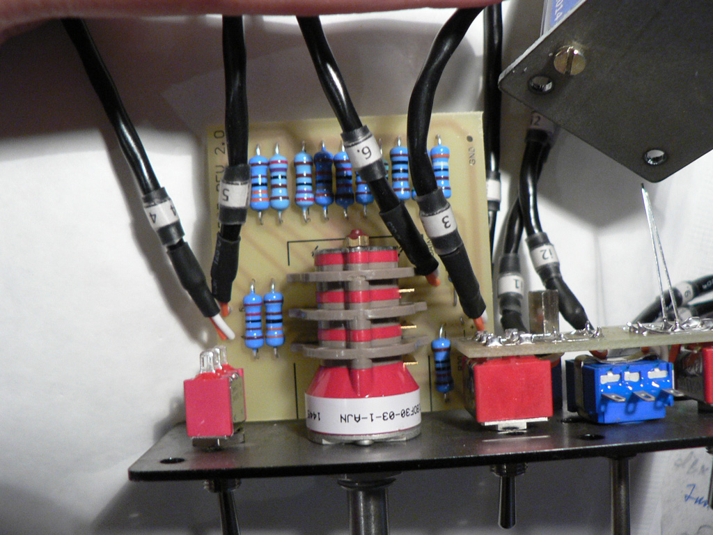
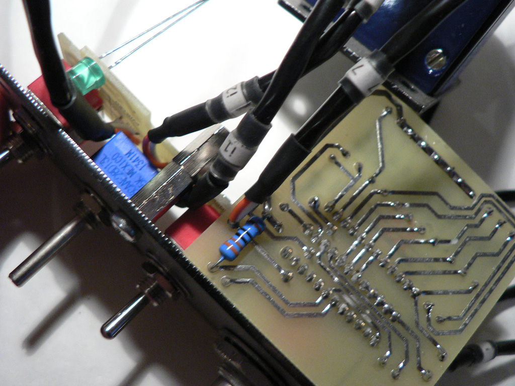
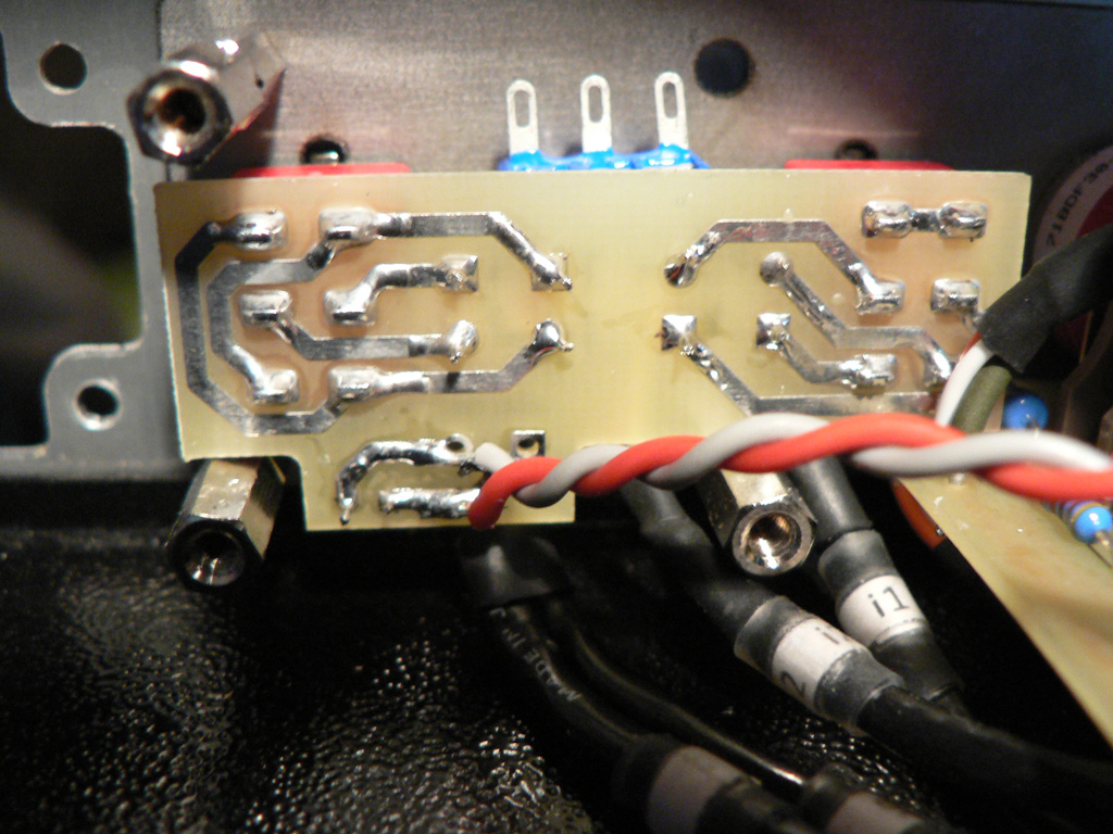
Solder wires "4", "5" and "6" to the corresponding pads on the Gain switch PCB.
Solder the wire "3" to the "In" pads of the Gain switch PCB.
|
 |
|
Solder the wire "7" to the bottom side of the corresponding pad on the Gain switch PCB.
|
 |
|
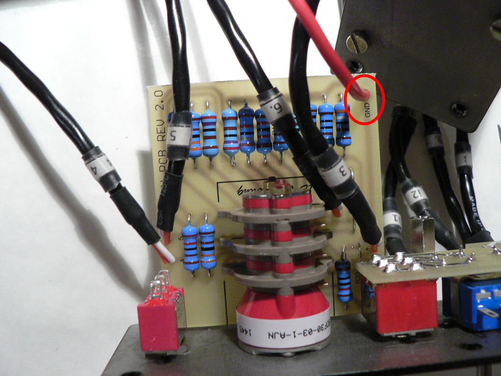
Solder the 16cm (6.3") piece of wire to the "GND" pad of the Gain switch PCB.
|
 |
|
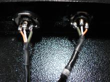
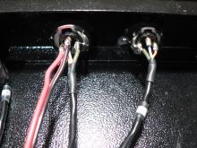
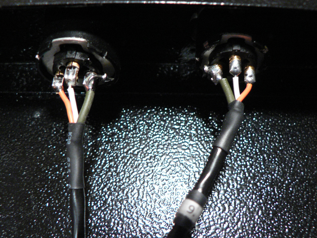
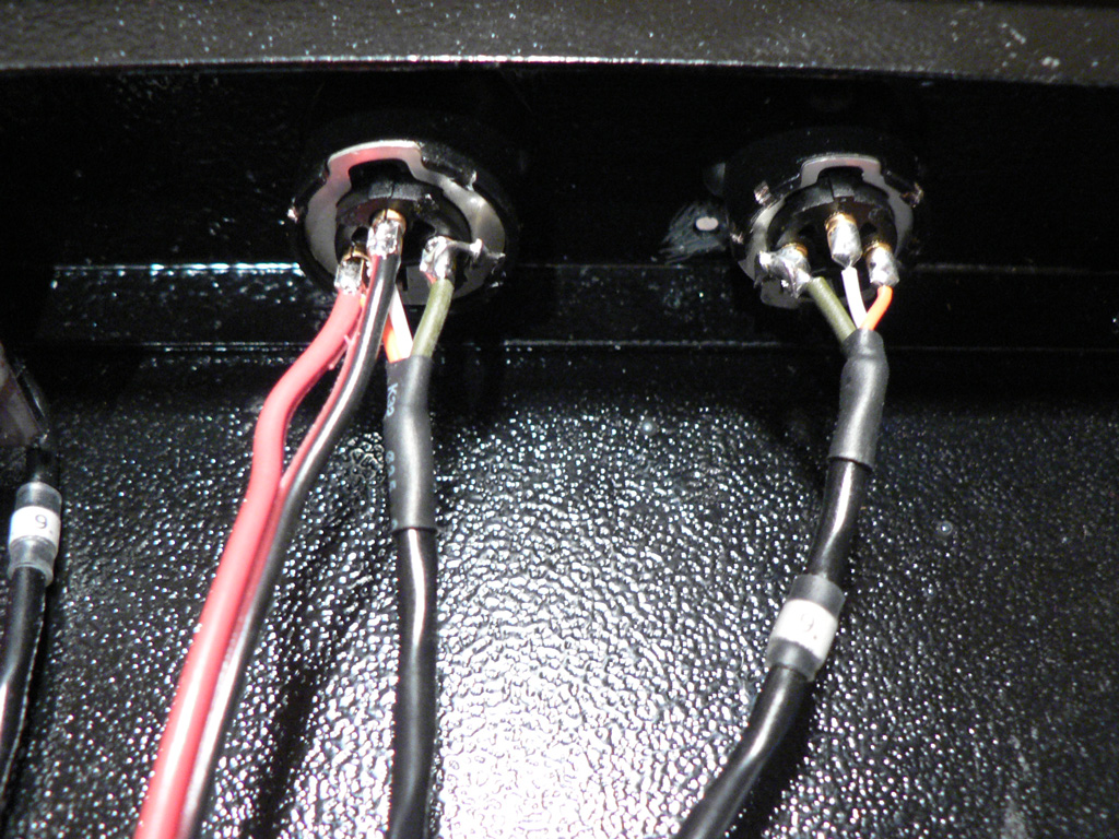
Solder mic in wire to the input XLR.
Solder wire "9" to the output XLR.
|
 |
|
Solder two 20cm (7.9") pieces of wire to pins 2 and 3 of the input XLR. These wires will feed phantom power from the main PCB to the mic. |
 |
|
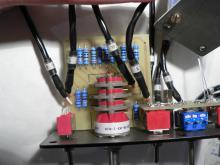
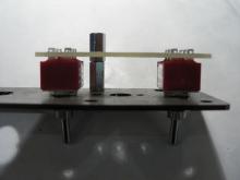
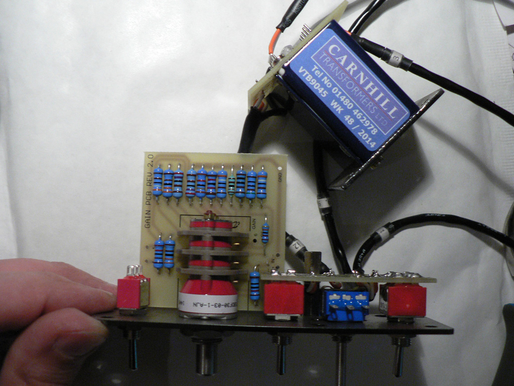
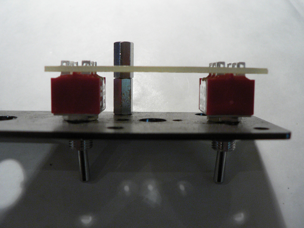
Screw the 20mm standoff to the lower hole of the front panel mounting bracket as shown on the photo.
This standoff will be used for input transformer mounting.
|
 |
|
Screw the front panel of the module to the frame front panel with provided socket screws and nuts. You may need to cut down the screws if needed.
Screw the mounting bracket using two 20mm standoffs as shown on the photo. Fix the bracket with two nuts on the other side (not show on the photo).
Guide the LED into the front panel hole. Solder the LED in place.
Solder two 27cm (10.6") pieces of wires to the LED pads.
|
 |
|
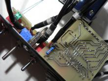
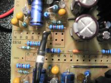
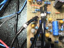
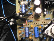
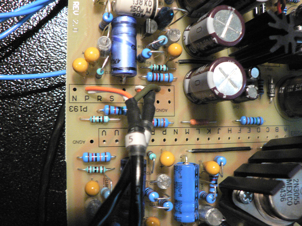
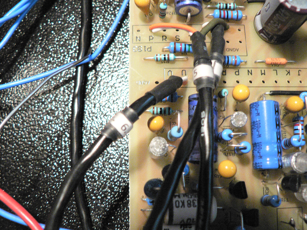
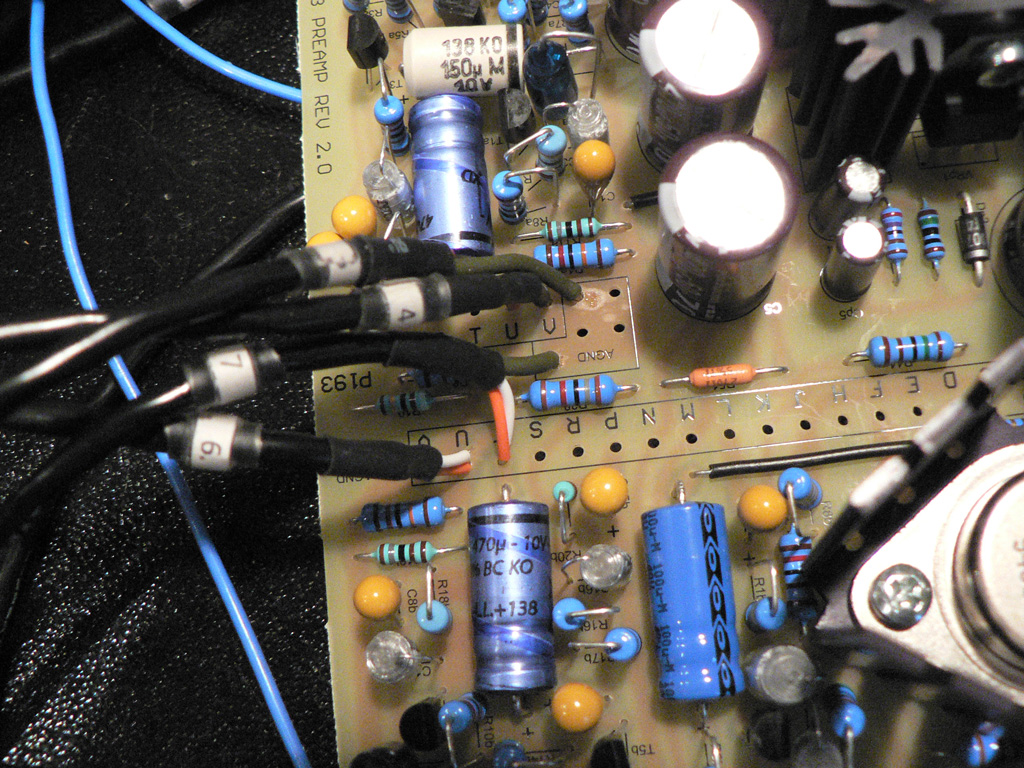
Solder the wire "4" to pads "U" (signal) and "V" (shield) of the P193.
|
 |
|
Solder the wire "5" to pads "P" (signal) and "AGND" (shield) of the P193.
|
 |
|
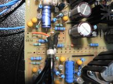
Solder the wire "6" to pads "U" (signal) and "V" (shield) of the P283 |
 |
|
Solder the wire "7" to the pad "T" (signal) of the P283 and "AGND" (shield) of the P193 |
 |
