Although module assembly is quite simple, pay careful attention to the wiring stage. There're a lot of wires, they all should go to the right places or the module will not work correctly.
|
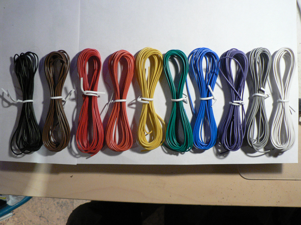
Now we are going to wire all other switch assemblies to the PCBs. There are a lot of connections between each switch assembly and PCB, so in order to keep the wiring and troubleshooting easier we need to establish the common color code system that will be valid for each and every connection. We suggest using a resistor colour coding scheme: 1 - black We will assign number and color to each connection during every step. |
 |
|
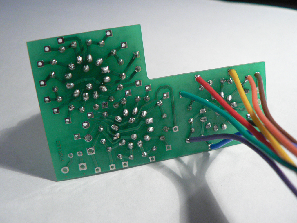
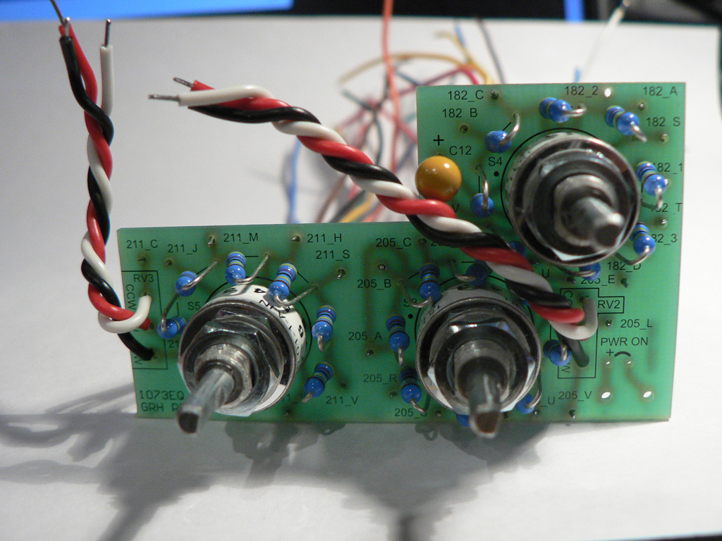
Let's start with the Presence switch. Prepare eight wires approximately 14 cm (5.5") each. Solder wires to the pads with names starting with "211_". We assigned the following colors to the connections: 211_B - black |
 |
|
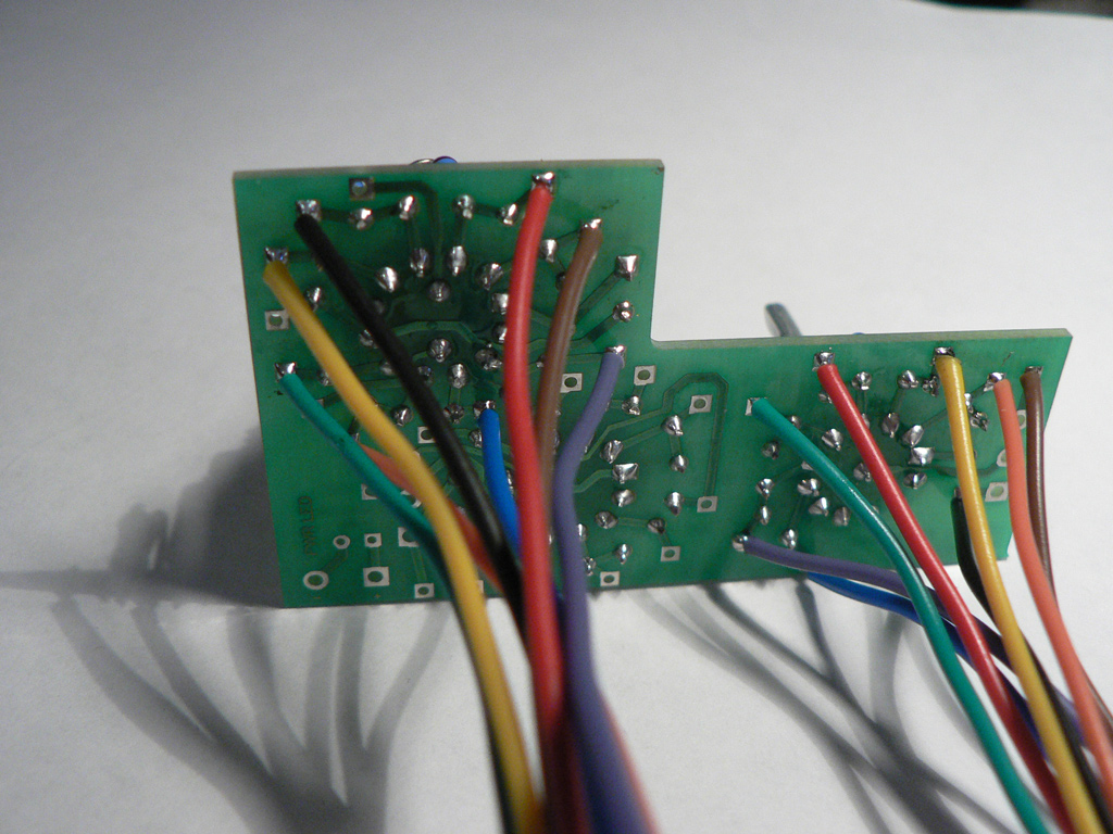
High pass section will be next. Prepare eight wires approximately 15 cm (5.9") each. Solder wires to the pads with names starting with "182_". We assigned the following colors to the connections: 182_A - black |
 |
|
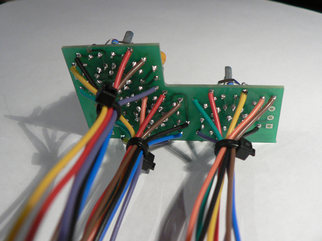
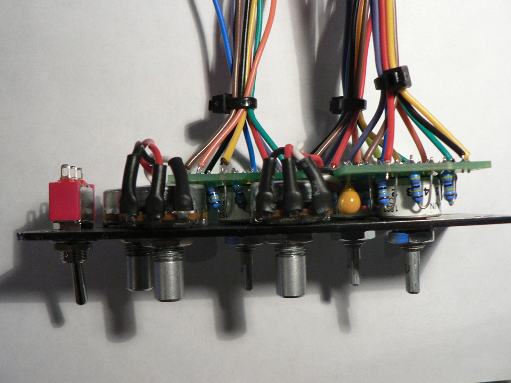
Finally, let's make the LF section. Prepare eleven wires approximately 16 cm (6.3") each. Solder wires to the pads with names starting with "205_". We assigned the following colors to the connections: 205_A - black Dress all wires with cable ties near the PCB as shown on the photo.. |
 |
|
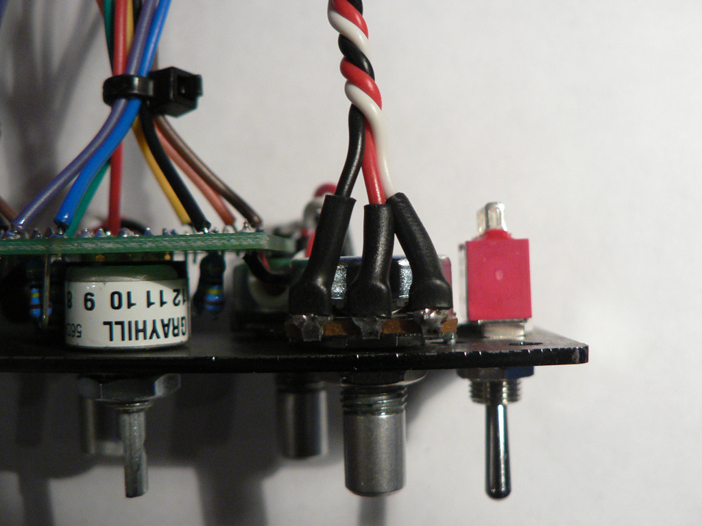
Prepare three wires approximately 7 cm (2,8") long, twist them together and solder to the RV2 pads (LF potentiometer). Prepare three wires approximately 5 cm (2") long, twist them together and solder to the RV3 pads (Presence potentiometer). Form the wires as shown on the picture |
 |
|
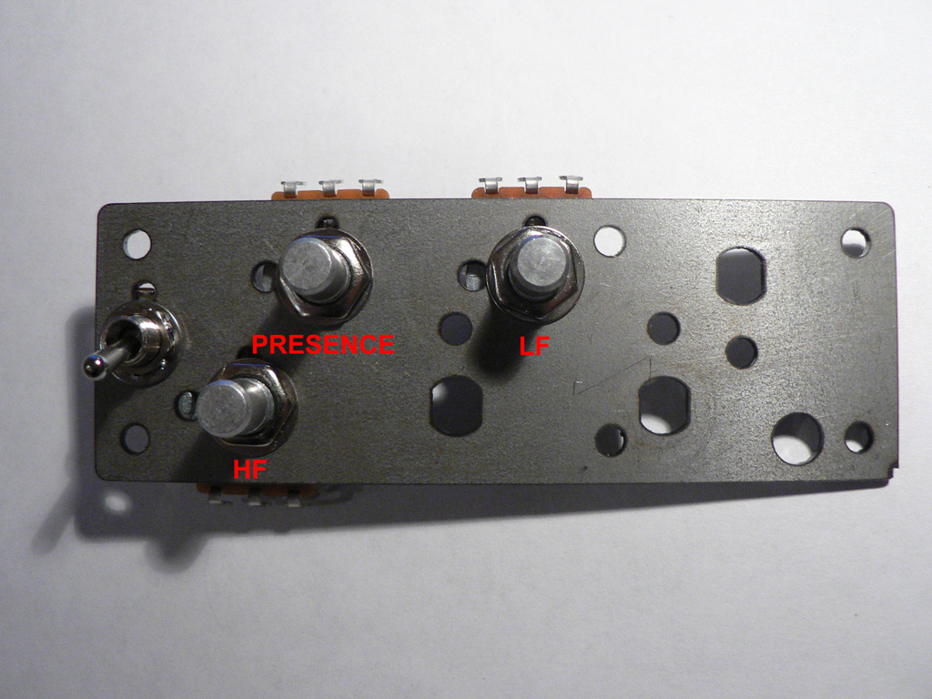
Fix the EQ in switch and three potentiometers to the mounting bracket as follows: HF and PRESENCE - 10K potentiometers |
 |
|
Solder wires to the Presence and LF potentiometers. Make sure to install insulating heatshrink tubing. |
 |
|
Prepare three pieces of wire approximately 14 cm (5.5") long. Twist them and solder to the HF potentiometer. Make sure to install insulating heatshrink tubing. |
 |
|
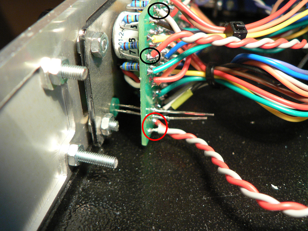
Insert the power on LED (observe polarity - longer leg is positive), but do not solder it in yet. Prepare two pieces of wire approximately 10 cm (4") long. Twist them and solder to the PWR ON pads on the PCB as shown on the photo (red circle). Prepare two pieces of wire approximately 18 cm (7") long. Twist them and solder to the 182_1 and 182_2 pads on the PCB as shown on the photo (black circles).
Install the 73EQ front panel and control mounting bracket to the 4-channel frame front panel. Guide the power on LED into the hole in the front panel and solder the LED into place.
|
 |
Now let's move on to the enclosure stuffing.