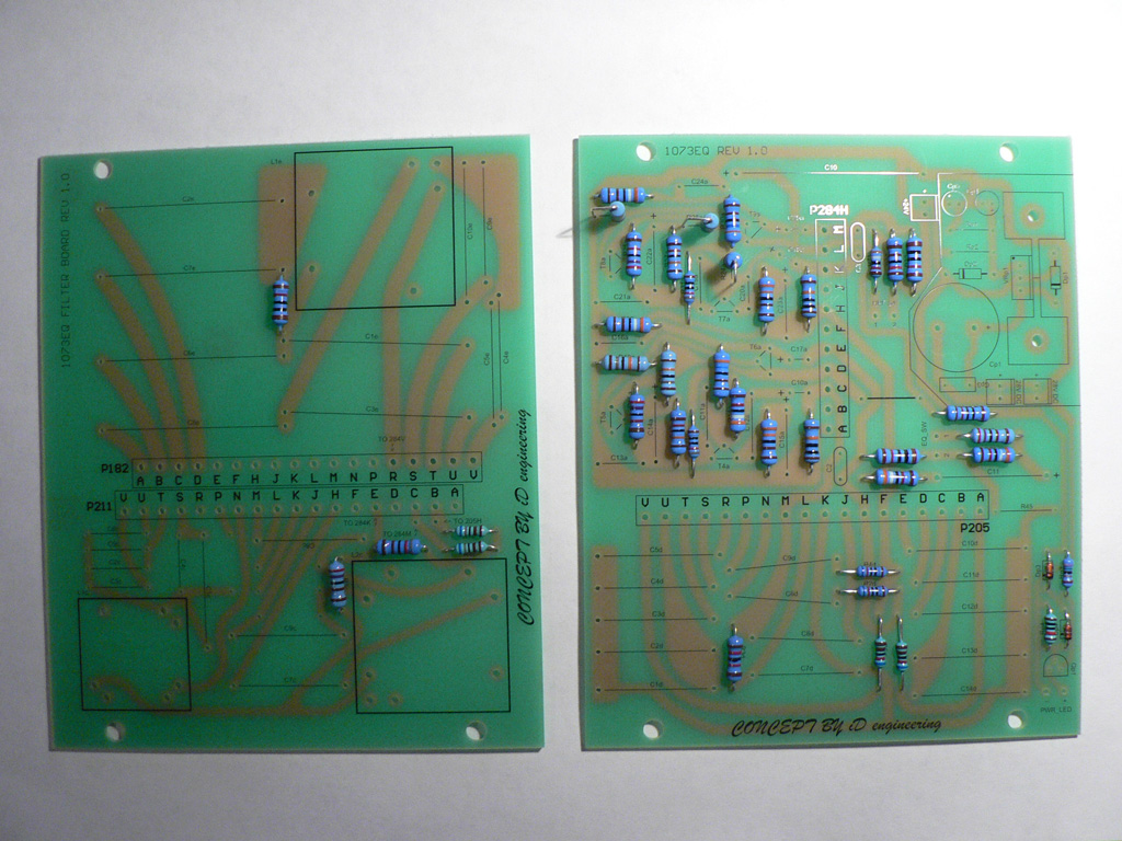
There are five PCBs in the 73EQ equalizer addon module: two filter PCBs and front panel switches PCBs (one for Grayhill switches option and two for Lorlin switches option).
Note that one filter PCB has an additional PSU section. Don't stuff this section - it was intended for ths standalone EQ module implementation and is currently not used.
|
Let's start with filter PCB.
Solder all resistors except Rp1 and Rp2. |
 |
|
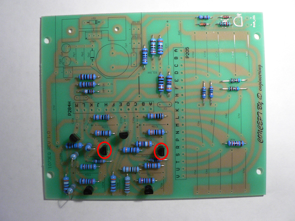
Now solder all transistors in the amplifier section. Note the transistors circled in red - those should have hfe>600 (T4a and T7a) |
 |
|
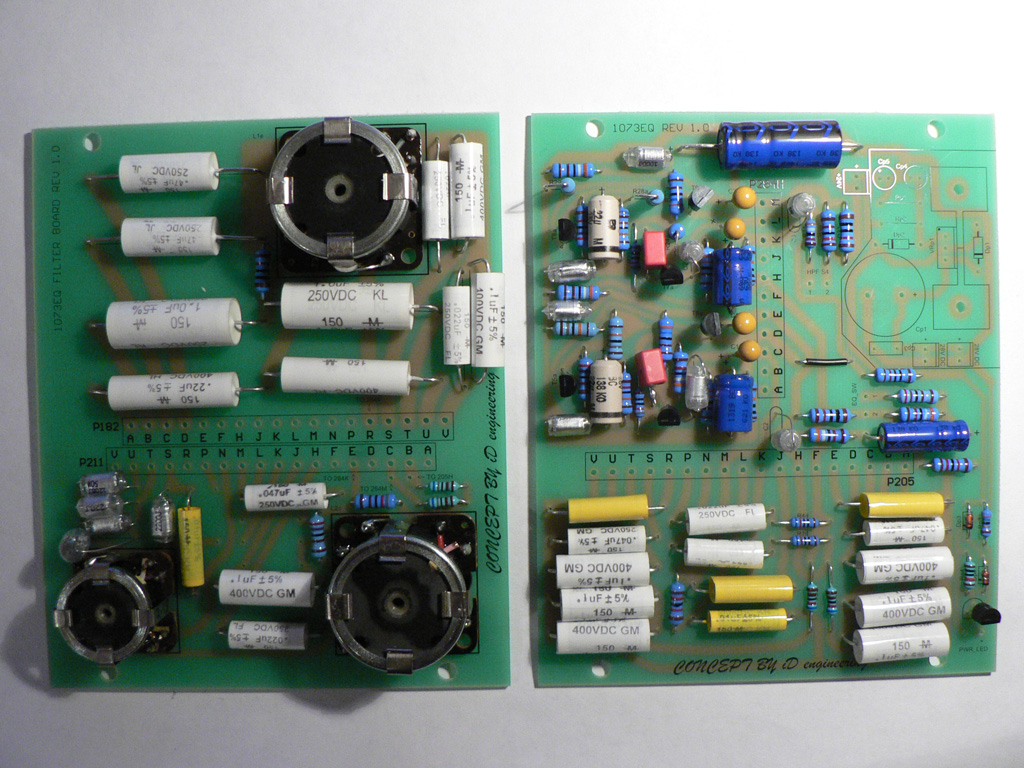
Finally, solder all capacitors and inductors. Don't forget to solder the wire link as well. |
 |
|
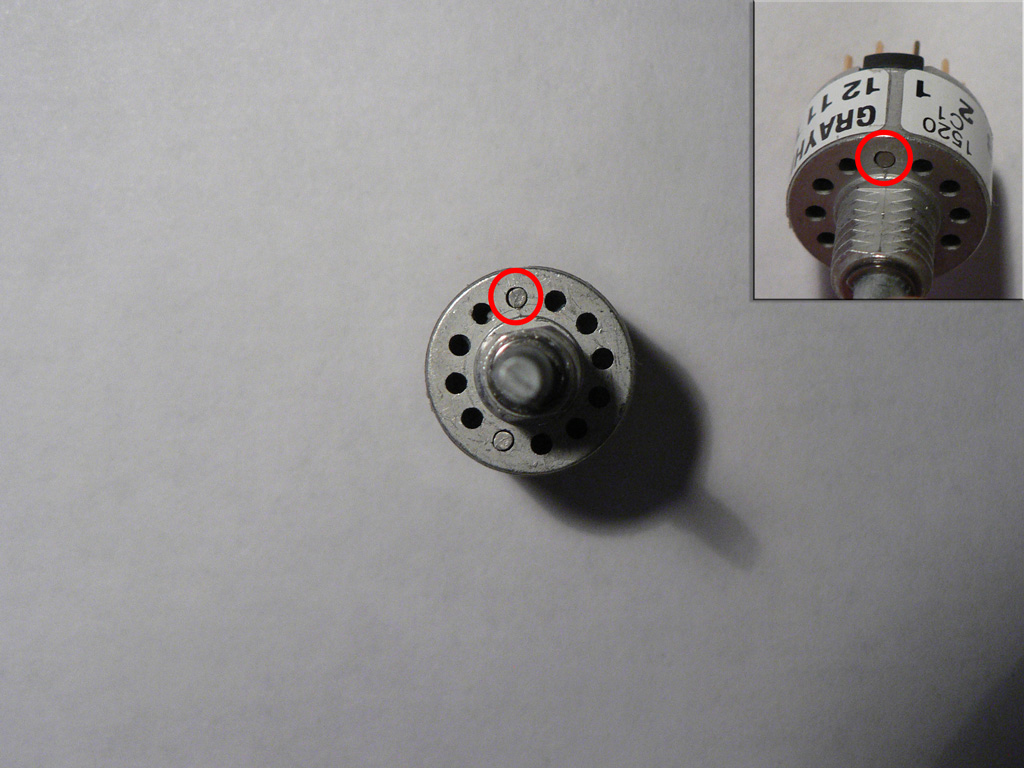
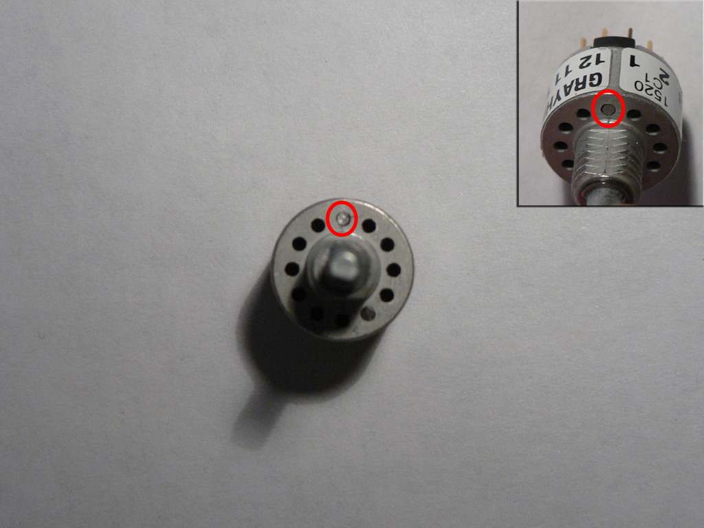
Let's prepare switches. Take 1 pole 12 positions switch and stop it down to 7 positions. With Grayhill switches, you will need two stop pins: one sets the stop before position 1, second sets the stop after position 7. IMPORTANT The switch should be set to the first position. Don't rotate the shaft of the switch before inserting the stop pins. If in doubt, check that the flat part of the shaft is looking at position 6 - this sets the switch to the first position. You may also check the common and first terminals of the switch with the DMM to be absolutely sure the switch is set to the first position. |
 |
| Take 2 pole 6 positions switches and stop them both down to 5 positions using the same procedure as above. |
 |
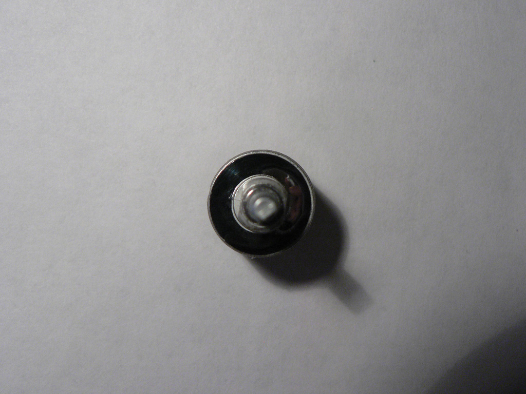
| Seal all switches with the adhesive tape supplied with the switches. |
 |
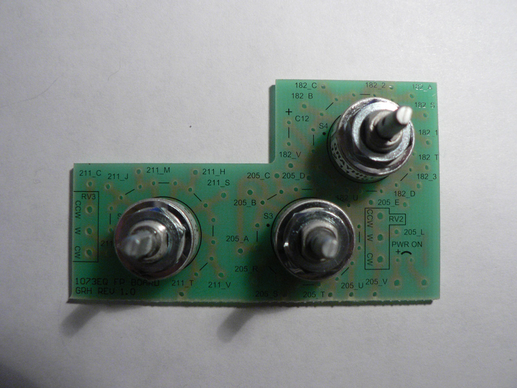
| Solder all switches to the front panel PCB. Note the dots on the silkscreen - they denote the first terminal of the switch. |
 |
|
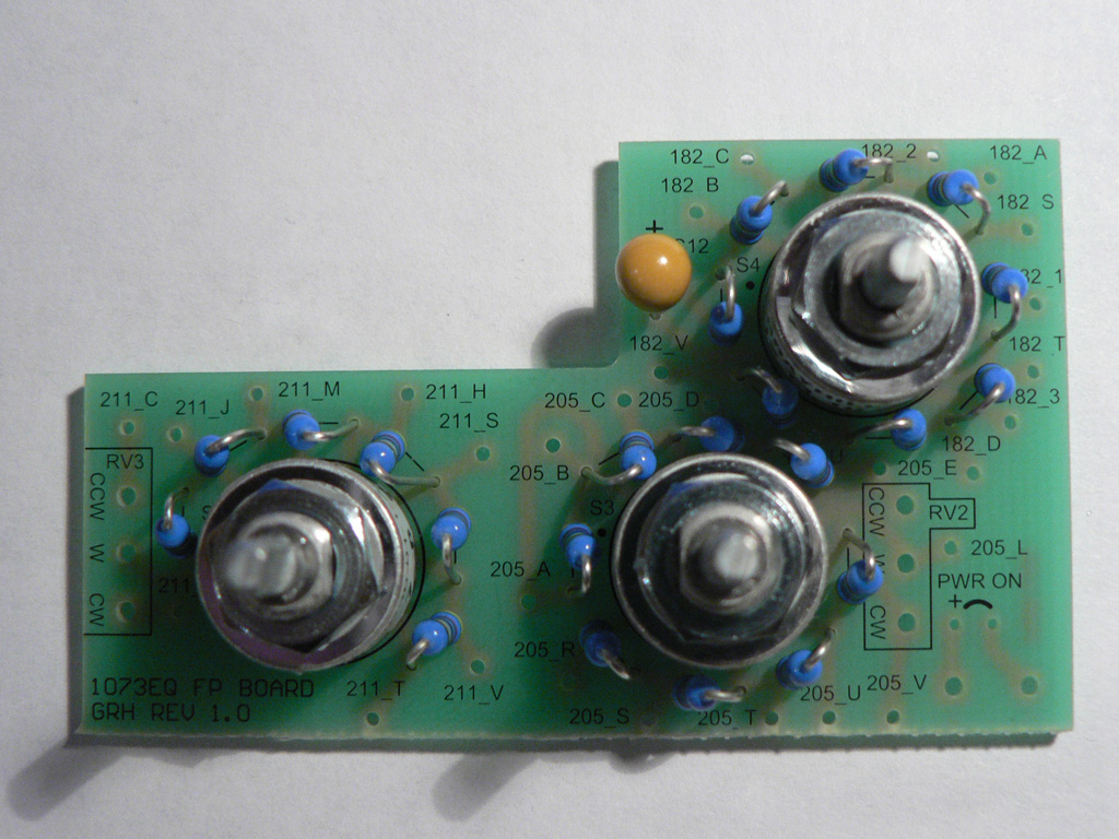
Solder 4.7M resistors and capacitor. |
 |
PCBs are ready. We can move on to Wiring the module