There are six PCBs in the 312 mic preamp module:
- Main PCB, which hosts the main preamp circuits. Voltage regulator section has designator with "p" suffixes.
- Front cotrols PCB, which hosts the switches and gain resistors.
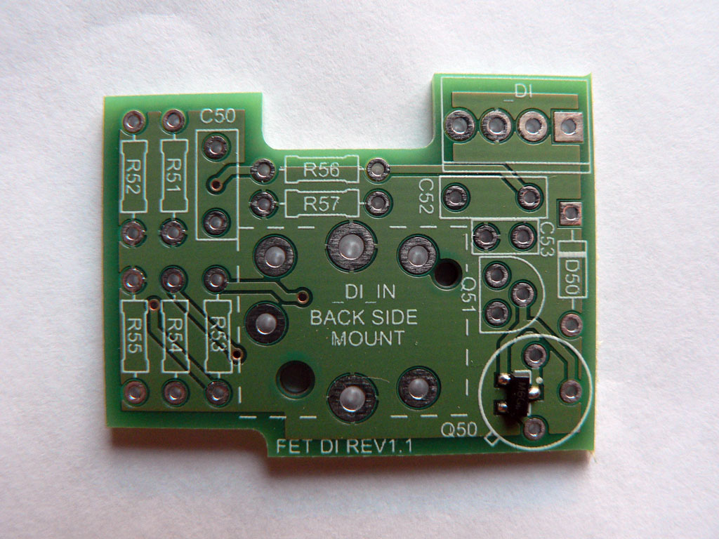
- FET DI PCB.
- Output trim PCB that hosts 600R t-pad.
- Discrete op-amp PCB.
- Gain potentiometer PCB - optional, for those who prefer to have a gain pot instead of a switch.
|
Solder the SMD transistor to the FET DI board first. If you're using through-hole version of the FET, skip this step and solder the transistor later. |
 |
||||||||||||||||||
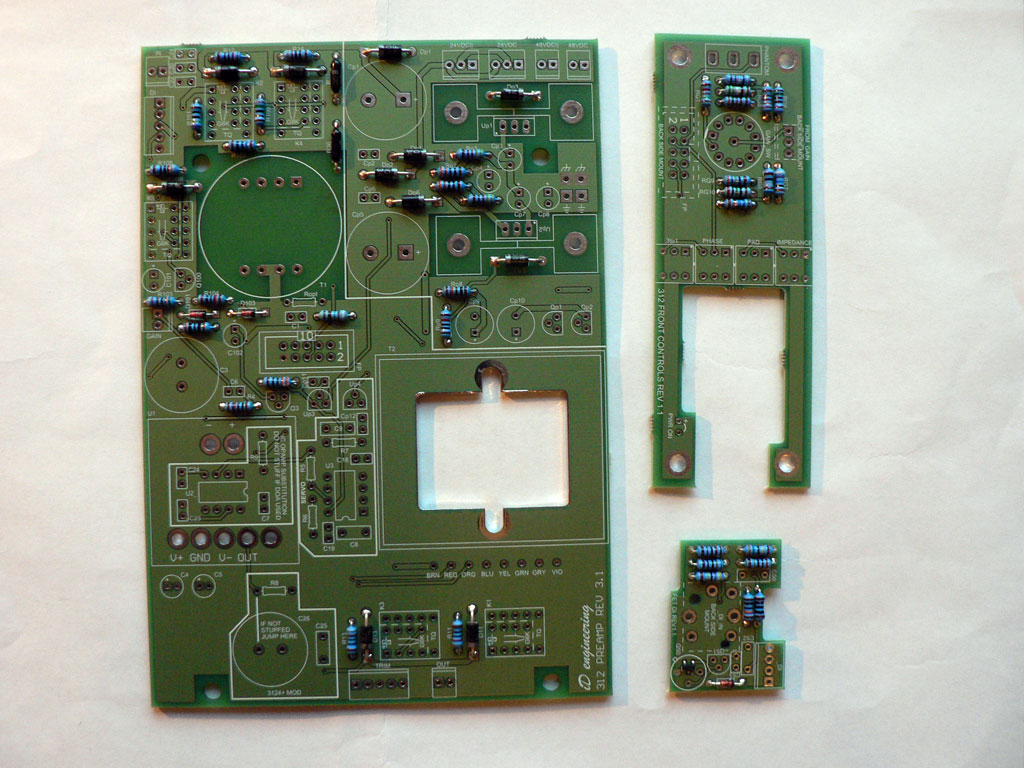
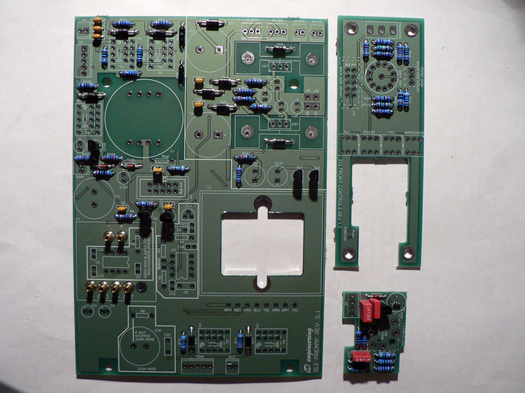
| Solder all resistors and diodes to the PCBs. |
 |
||||||||||||||||||
|
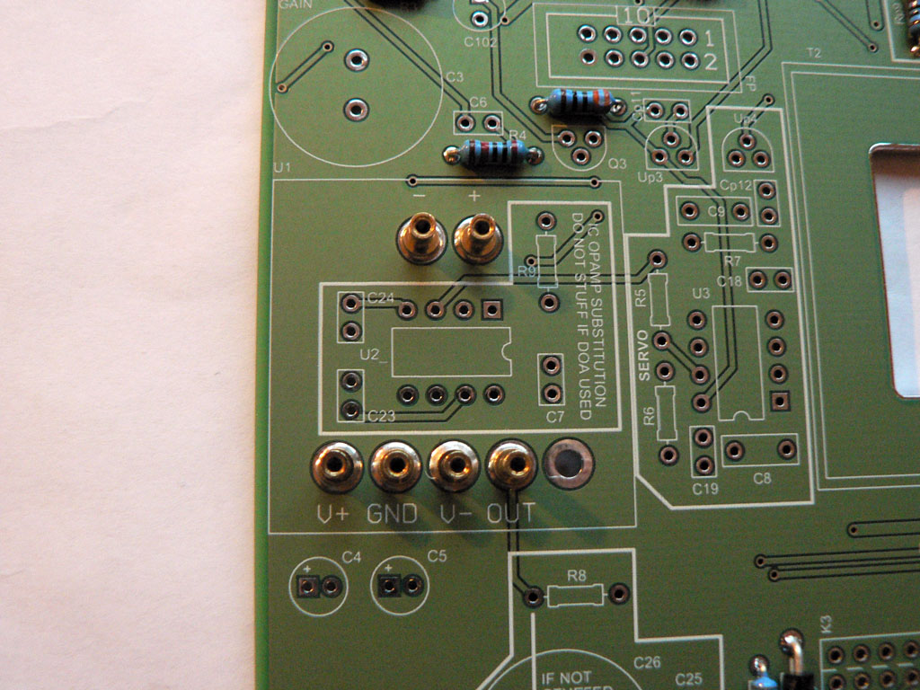
Solder MillMax sockets as shown on the photo. Make sure that they are perpendicular to the PCB. Please note that one PCB pad is left unpopulated. |
 |
||||||||||||||||||
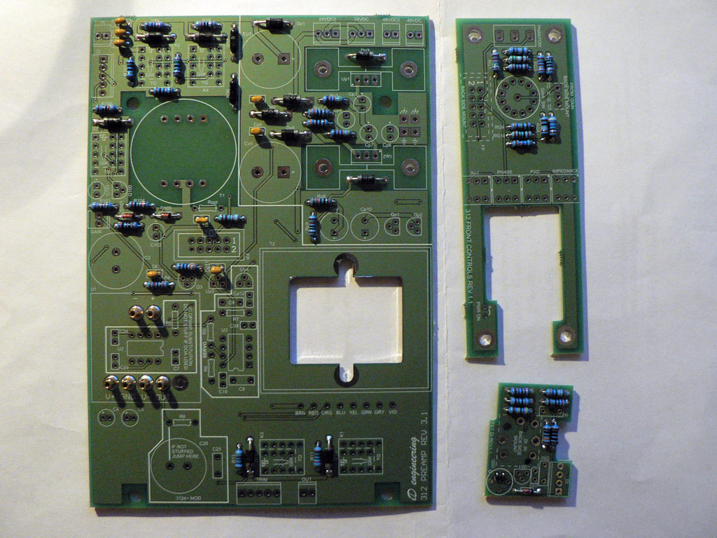
| Solder all ceramic capacitors. |
 |
||||||||||||||||||
|
Solder all film capacitors and transistors. |
 |
||||||||||||||||||
|
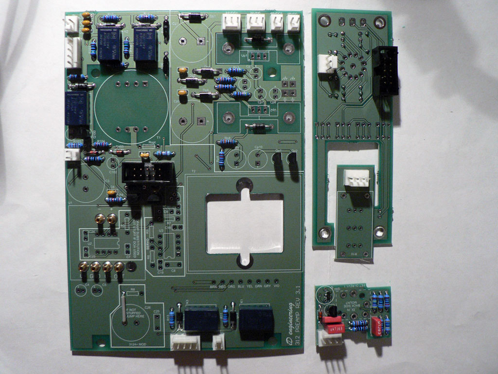
Solder all relays and connectors. Note that connectors on the front controls PCB are mounted on the back side of the PCB. If you're not going to install the 3124+ mod, solder the wire link as noted on the PCB. |
 |
||||||||||||||||||
|
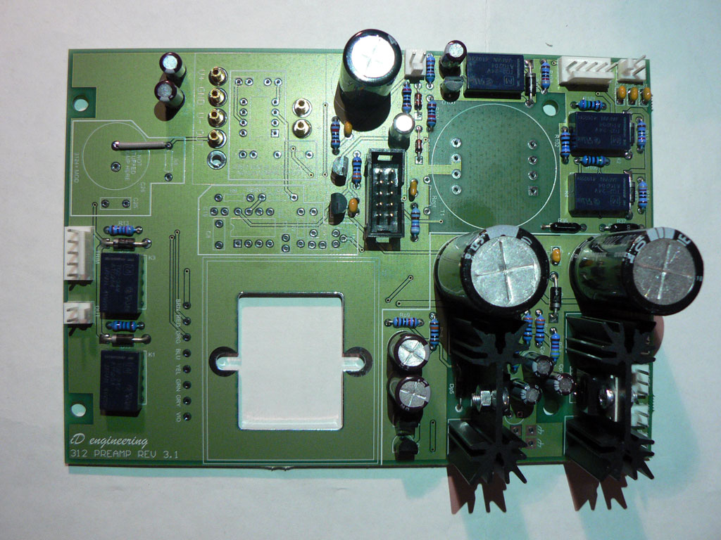
Solder all the remaining capacitors to the main PCB. Mount voltage regulator on the heatsink and sloder them to the PCB (do NOT mount the regulator to the heatsink after soldering - this will put stress on both the chip and solder joints). Solder heatsinks to the PCB pads as well (this is purely for mechanical reasons). |
 |
||||||||||||||||||
|
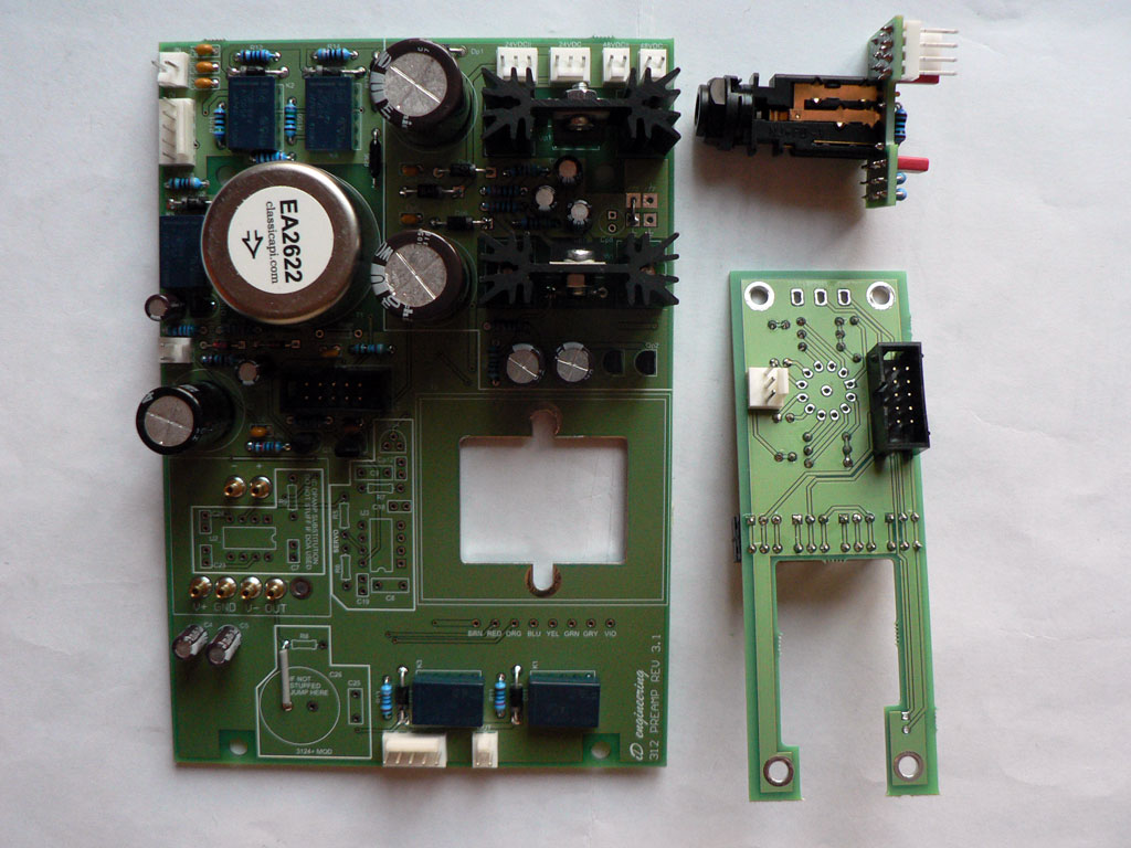
Solder the input transformer and DI jack socket to the PCBs. The first pin of the transformer is denoted with the square pad on the PCB. |
 |
||||||||||||||||||
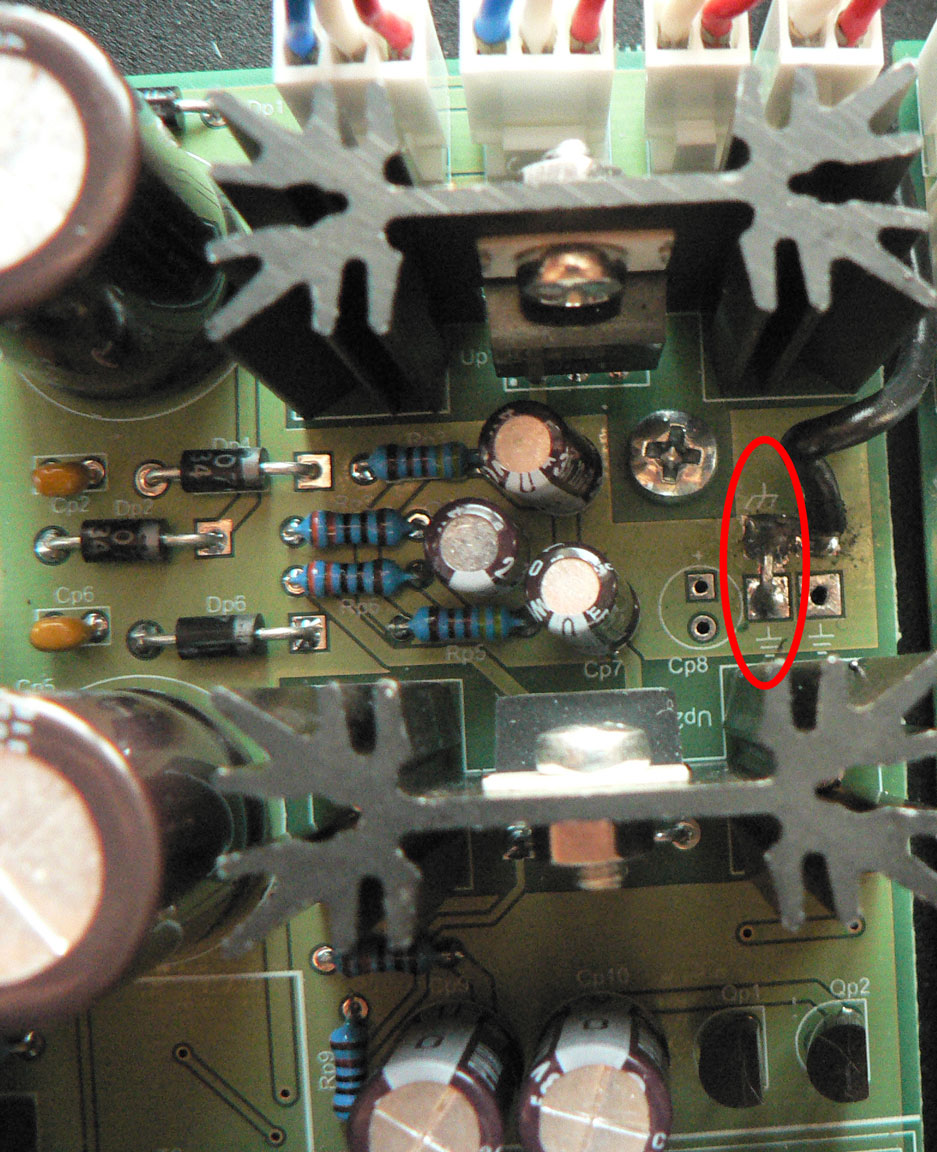
| Solder a wire link between audio and chassis grounds as shown on the photo (circled in red). |
 |
||||||||||||||||||
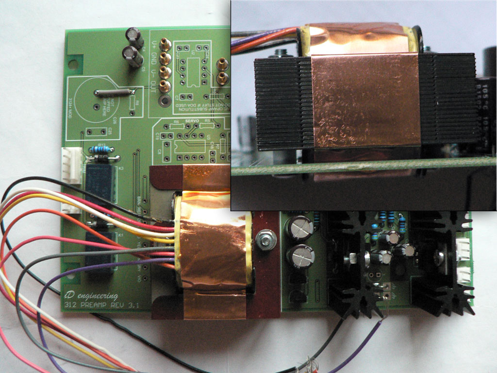
| Install the output transformer using M3x25 screws as shown on the photo. Use plastic stand-offs to offset the transformer from the PCB surface. |
 |
||||||||||||||||||
|
Trim the output transformer leads and solder them according to the color scheme on the PCB. Important! Color code on the PCB is for EA2503 output transformer. For other output transformers use the table below:
|
|||||||||||||||||||
We can move on to the Front controls