Checkout us now open. Please read here before ordering.

Assembling the module

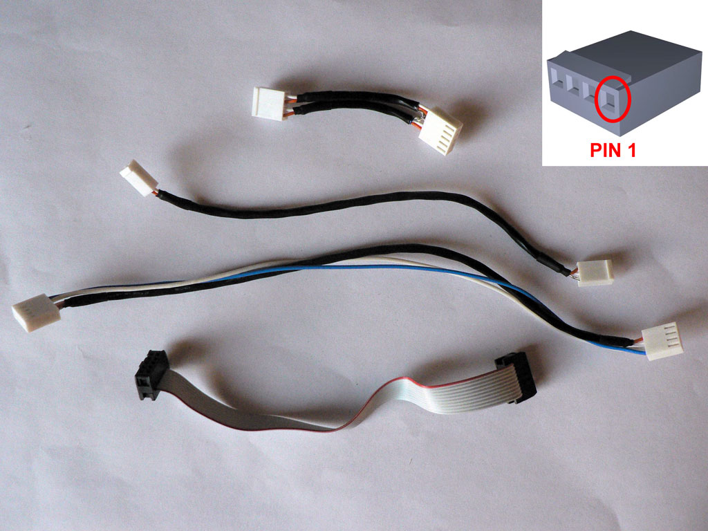
Prepare the following cables (listed as pictured on the photo, top to bottom):

  • Output trim - 7 cm (2.8"), 2 pieces of shielded twisted pair:
    • Pinout at one side as follows:
      • Pin 1 - Hot 1
      • Pin 2 - Cold 1
      • Pin 3 - Shield
      • Pin 4 - Hot 2
      • Pin 5 - Cold 2
    • Pinout at other side as follows:
      • Pin 1 - Hot 1
      • Pin 2 - Cold 1
      • Pin 3 - Hot 2
      • Pin 4 - Cold 2
  • Gain switch - 17 cm (6.7"), shielded twisted pair:
    • Pinout at one side as follows:
      • Pin 1 - Hot
      • Pin 2 - Cold
      • Pin 3 - Shield
    • Pinout at other side as follows:
      • Pin 1 - Hot
      • Pin 2 - Cold
  • DI board - 24 cm (9.4"), shielded twisted pair and 2 wires:
    • Pinout at both sides as follows:
      • Pin 1 - Wire 1
      • Pin 2 - Wire 2
      • Pin 3 - Cold
      • Pin 4 - Hot
      • Pin 5 -Schield
  • Front controls - IDC, 14 cm (5.5"). In order to install IDC headers you need to apply even pressure on the connectors. We used vise for this task. Make sure that the first wire (red) goes to the first pin of the connector (often marked with a triangle, arrow or the like).

Input and output XLRs are connected with shielded twisted pairs, shield is soldered at the XLR side only, install Molex connector on the other side, pinout as follows (for both cables):

  • Pin 1 - Hot
  • Pin 2 - Cold

Input XLR cable should be 8 cm (3.1") long. Output XLR cable should be 22 cm (8.7") long.

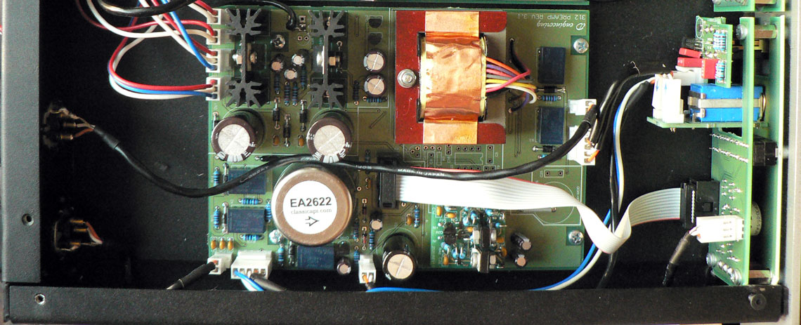
Install and connect all boards.

Run a wire from a link between grounds to common star ground point at the chassis (most often this is earth contact at the IEC inlet).

Connect power to the 24VDC and 48VDC connectors (note: 24VDC|| and 48VDC|| a connected in parallel to the 24VDC and 48VDC respectively. These connectors are used to daisy-chain power from one module to the next).

  • 24VDC and 24VDC|| pinout:
    • Pin 1 = +24V
    • Pin 2 = GND
    • Pin 3 = -24V
  • 48VDC and 48VDC|| pinout:
    • Pin 1 = +48V
    • Pin 2 = GND