WARNING! Read this before proceeding any further!
Wiring PSU involves working with potentialy lethal voltages. Mains voltage can kill you!
Attempt wiring only if you know what you are doing. Otherwise get help from a certified technician. In no case RackNeve.com and its owners should be held liable for any damage to equipment, injury or death of operator. If you move on you accept these terms and agree to NOT hold anybody liable for your actions.
Ok. Hopefully your are not scared enough to drop the build and run away. Let's move on to the PSU and mains wiring. Be extra cautious while doing this and NEVER work on live circuit - always make sure that mains power cord is unplugged before putting your hands or soldering iron inside the unit.
|
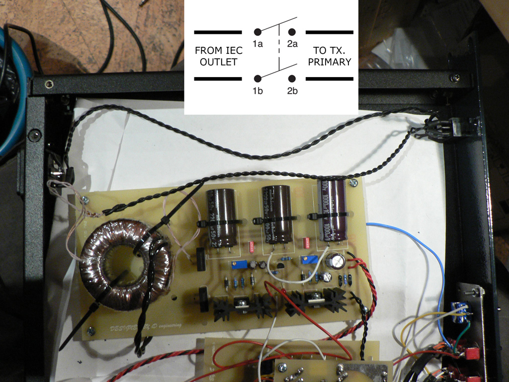
Connect IEC receptacle to one pair of the power switch contacts. Connect mains transformer primary to another pair of power switch contacts.
If you live in the country with 110V mains voltage, you need to connect transformer primaries in parallel. For 220V operation connect primaries in series.
Put heatshrink tubing arount all exposed contacts!
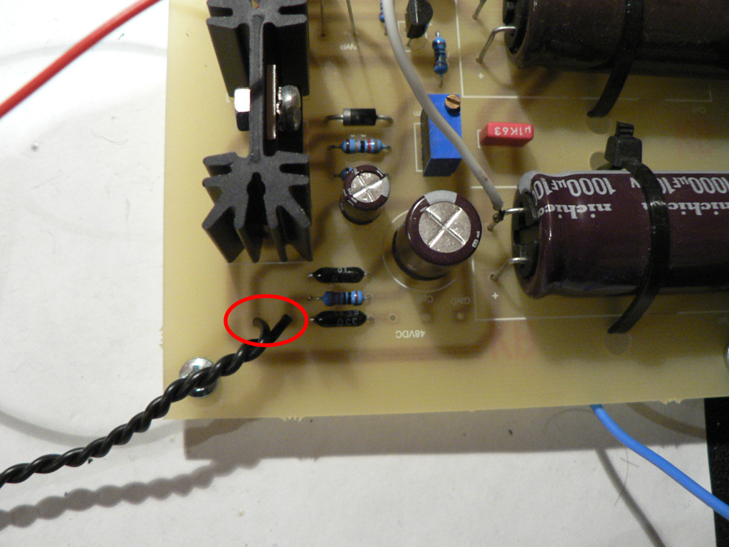
In order for PSU to work correctly we need to install ground wire link between +24V and +48V sections. Solder a temporary wire link between "-" terminals of Cp1 and Cp6. |
 |
|
Before making connections to the main PCB, we need to check and adjust voltages of the PSU.
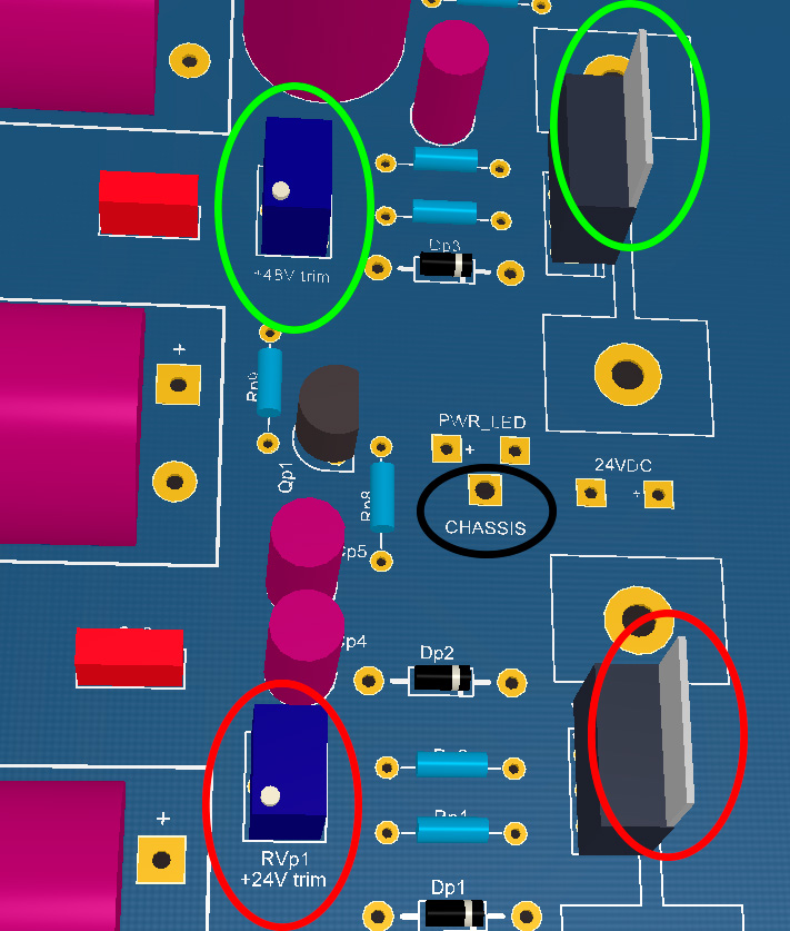
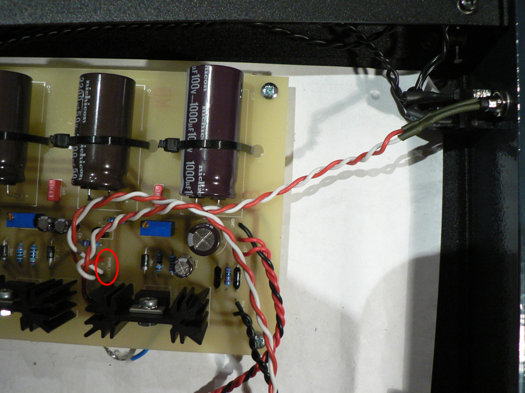
Connect the PSU chassis pad (circled in black) to the mains safety earth (one of the IEC receptacle screws that connects mains earth to chassis).
Install 0.5A fuse in the receptacle.
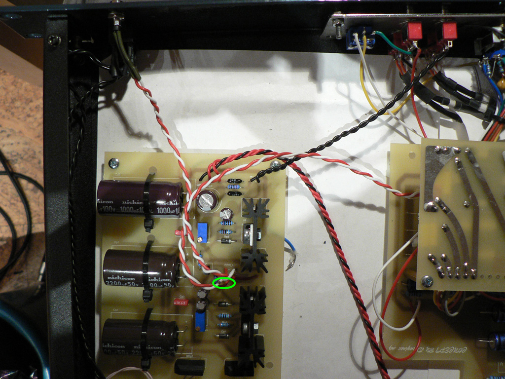
Turn on the power and measure voltages at the tabs of voltage regulators (you can now use any exposed metal of the chassis as your ground reference. We used the inner side of threaded insets for that). Adjust RVp1 (circled in red) to read +24V at LM317, Adjust RVp2 (circled in green) to read +48V at TL783.
If you notice any strange smell, smoke or heating turn off the power immediately and check connections. |
 |
|
Connect lower (normally open) contacts of the "Phantom" switch to the "PH_SW" terminals on the PSU board. |
 |
|
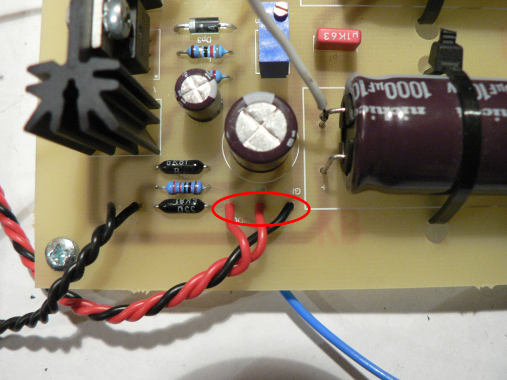
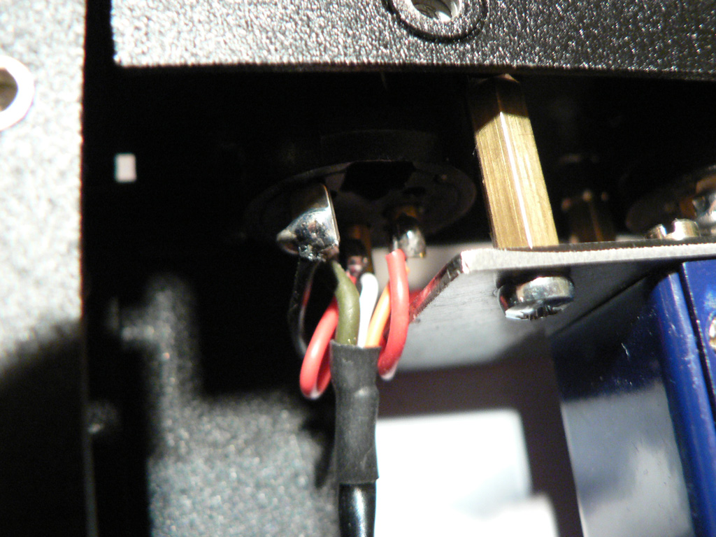
In order to connect phantom power to the microphone input XLR you need to twist tree wires. One of them will be ground, other two - +48V. Solder the wires to the "48VDC" terminals on the PSU board. Note that on the picture the black wire is ground, and red wires are +48V. |
 |
|
Connect opposite ends of wires to the microphone input XLR. Solder ground wire to pin 1/chassis bond. Solder +48V wires to pins 2 and 3.
Remove temporary wire link between Cp1 and Cp6.
Turn on the power. Activate the phantom power swicth and measure voltages between pins 1 and 2 and between pins 1 and 3 of the microphone input XLR. You should read equal voltages in bothe cases. Otherwise carefully check your wiring. |
 |
|
Install the power indicator LED and connect it to the "PWR_LED" terminals on the PSU board. Make sure to connect "+" wire of the LED indicator to the "+" terminal on the PCB.
Do not forget to put heatshrin tubing around LED wires.
Turn on the power and check that the LED is working. |
 |
|
Finally we can apply power to the preamp PCB.
Solder wires from PSU "24VDC" terminals to the main board "PWR" terminals.
IMPORTANT! Make sure your RV1b trimmer wiper is set in the middle before applying power!
Turn on the power and check that your +24V stays the same. If your voltage sags it means there is short circuit somewhere. You need to check your solder joints and make sure there are no solder bridges and cold joints. |
 |
|
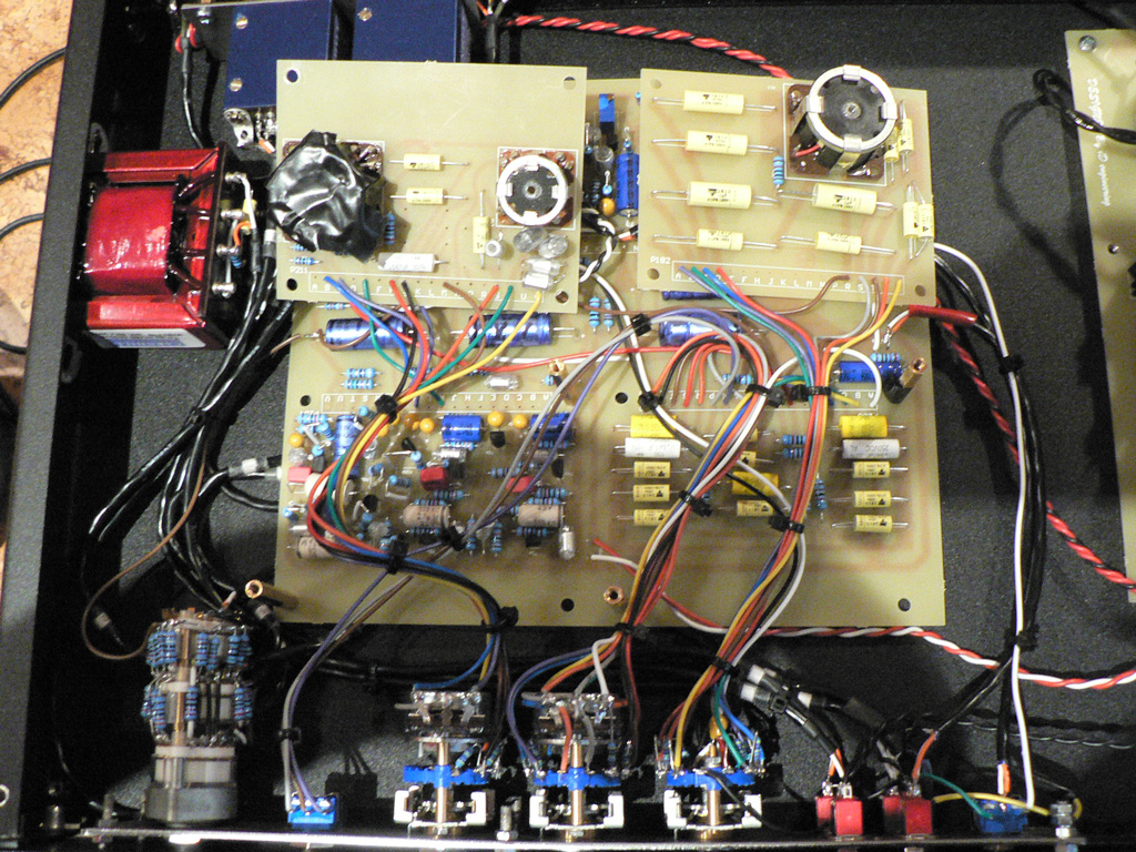
Now is a good time to clean up the wiring. We suggest using wire ties for this.
Pay attention to the large inductor on the B211 board. We suggest isolating it's frame because it may accidentally short the components on the motherboard underneath it. |
 |
Now that the unit is working we need to test it and adjust for proper operation.