Yes, we hate metal work as much as you do. But it is impossible to avoid this step. We did our best to make it easy for everybody. Bear with us, it will not take much time.
Please, download drill templates here.
You will need to print and cut out these templates. Make sure you do not have any scaling turned on in your printer settings. It is also a good idea to check all templates against the PCBs to make sure that all holes align.
|
We will start with drilling mounting holes in the bottom cover. For this you will need to print out the trill templates that can be found here.
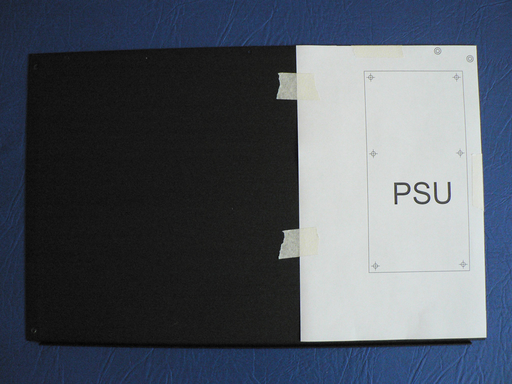
Place the bottom cover with the front lip up and towards you as shown on the picture. Cut out the PSU drill template and stick it to the bottom cover. Make sure to align the top right angle of the drill template with that of the bottom cover. Check that double circled holes on the template align with the cover holes.
Use a center punch tool to mark the centers of the PCBs mounting holes. After that drill the holes with the 3mm drill bit. |
 |
|
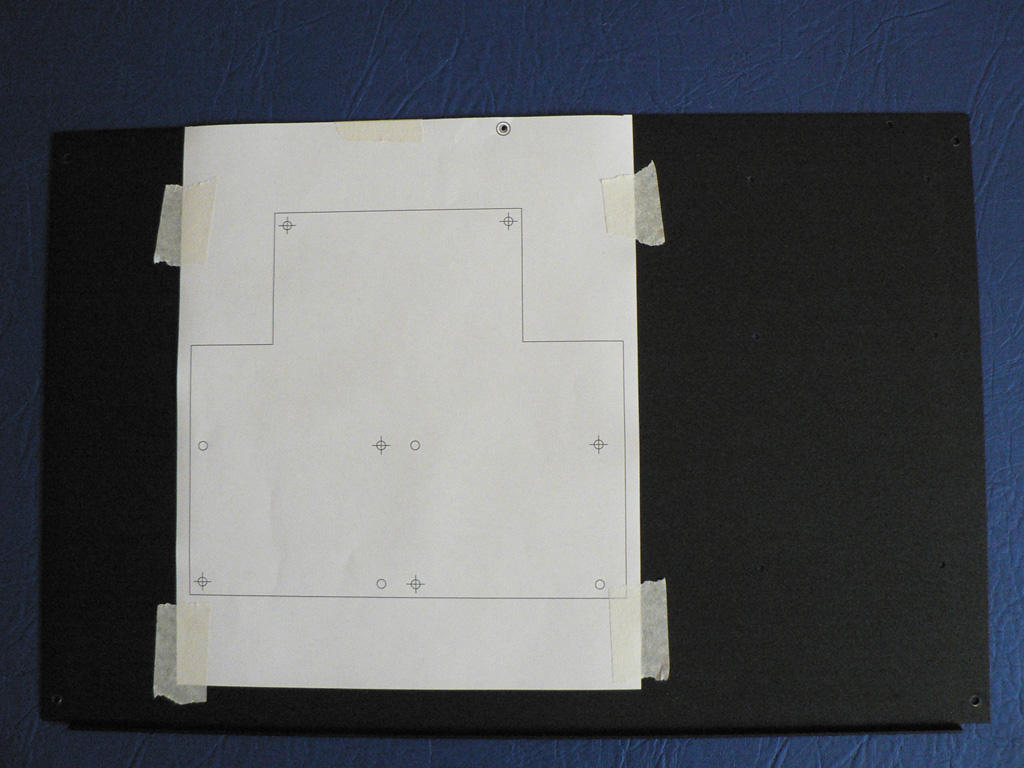
Now we need to drill the holes for mounting preamp PCBs. If you look closely at the drill template you will find that some holes have crosses inside and some do not. We suggest that you drill only those six holes that have crosses inside. They are sufficient for secure mounting of the PCBs. But of course you can drill all ten holes if you want to.
Cut out the Motherboard drill template and align the double circled hole with the top center hole of the bottom cover as shown on the picture.
Use center punch tool to mark the holes centers and drill the holes with the 3mm drill bit. |
 |
|
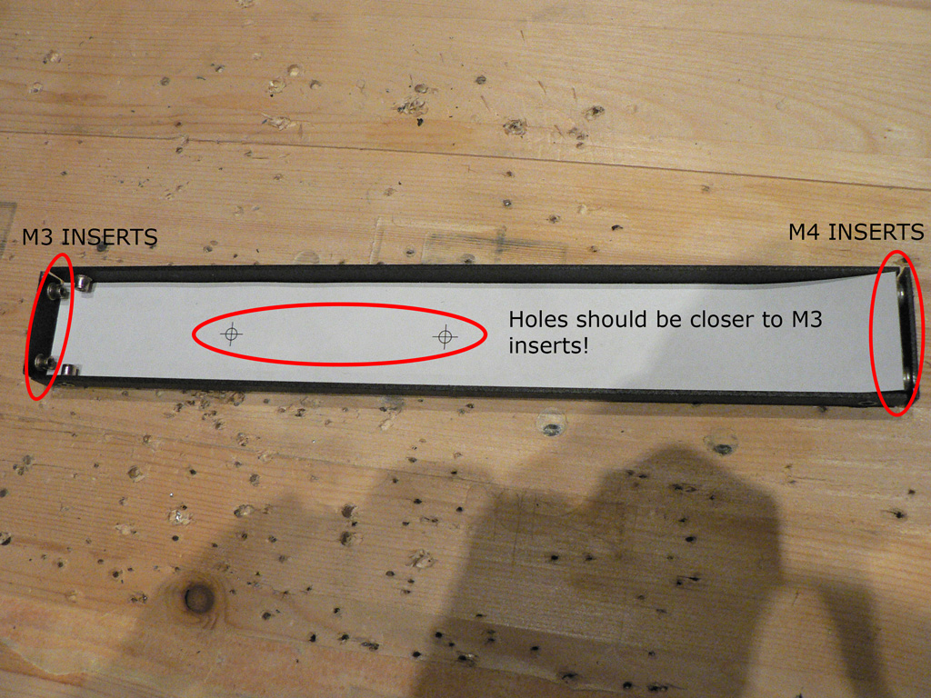
Cut out the Output Transformer drill template. Take one of the side parts and put the template inside. Make sure that the template holes are closer to the M3 threaded inserts of the side part.
Center punch the holes and drill them with the 3mm drill bit. You can use 4mm drill bit here, but keep in mind that M4 bolts have bigger head and this may cause inconvenience when putting the 1073 clone in the rack mount. |
 |
|
Now couple of thoughts regarding mounting.
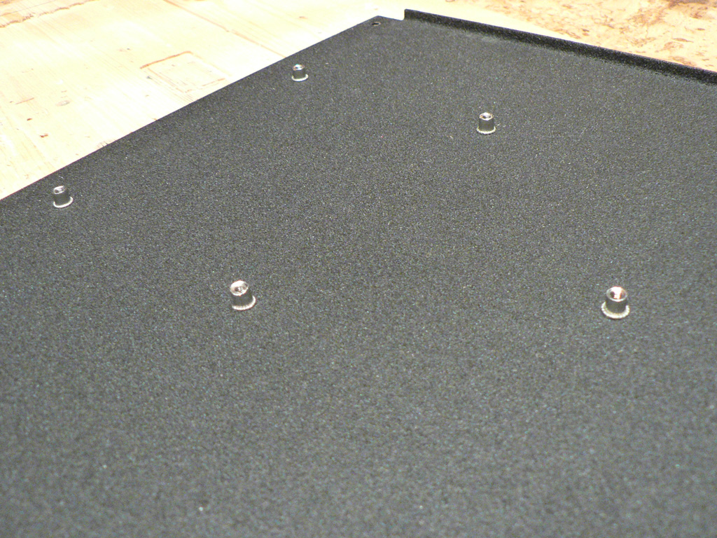
In the DIY world people often use stand-offs for PCB mounting. And it is easy to see why: they are easy to work with, they do not require special tooling to install and they come in a variety of shapes and forms. However, they have one disadvantage: you need a screw to fix them. In our case this means that heads of the screws will stick out from the bottom of the unit. This looks untidy and can cause damage to the surface finish of the top lid of the device that is installed lower in a rack.
In our build we used threaded rivets instead. You can see them installed on the photo. Once installed they are approximately 5mm high. We used rivets with low-profile head which is less than 1mm above the surface. The only disadvantage to these rivets is special tooling. For experienced DIY enthusiast we suggest that you look into these rivet nuts - we are sure you will like them a lot. |
 |
Hopefuly you managed to complete this step. Now we can move on to the enclosure stuffing.