Now we need to put everything inside the enclosure. We are very close to the final steps.
|
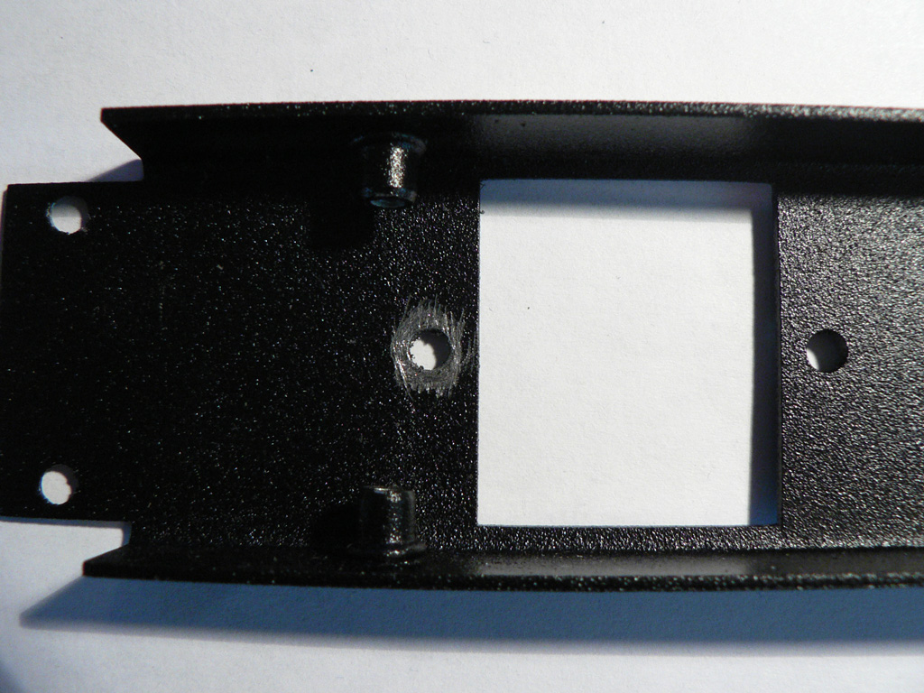
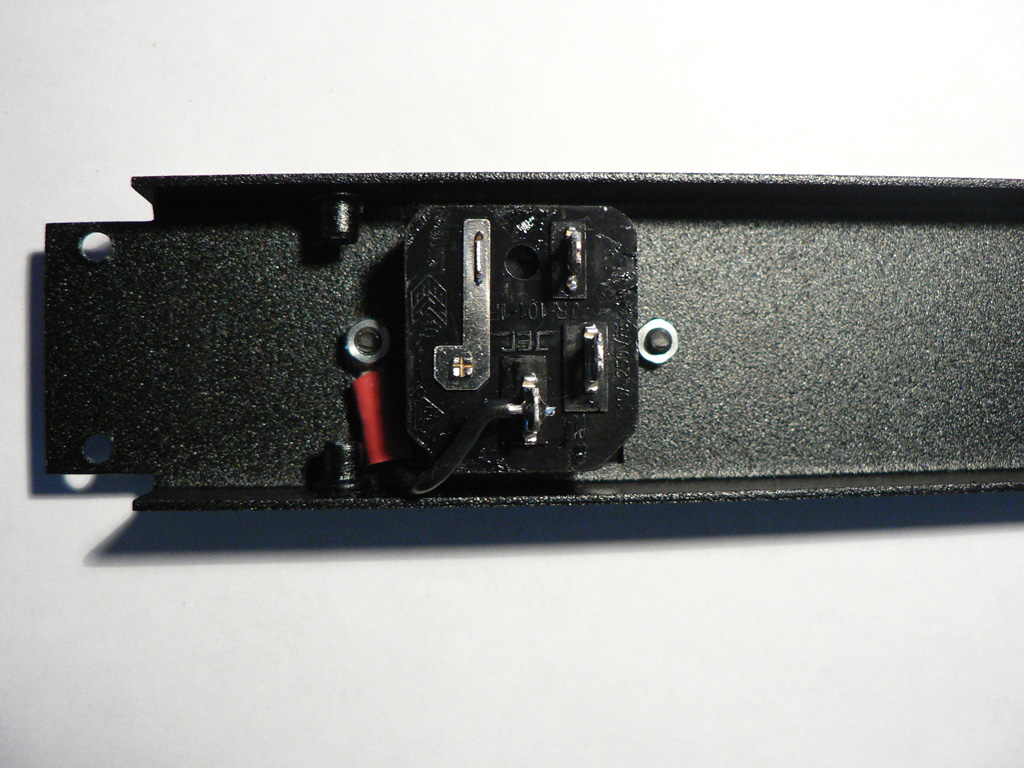
Take the back panel and remove the paint around one of the mounting holes for the IEC receptacle. This will be our safety earth connection (all exposed metal parts should be connected to the mains earth conductor for safety). |
 |
|
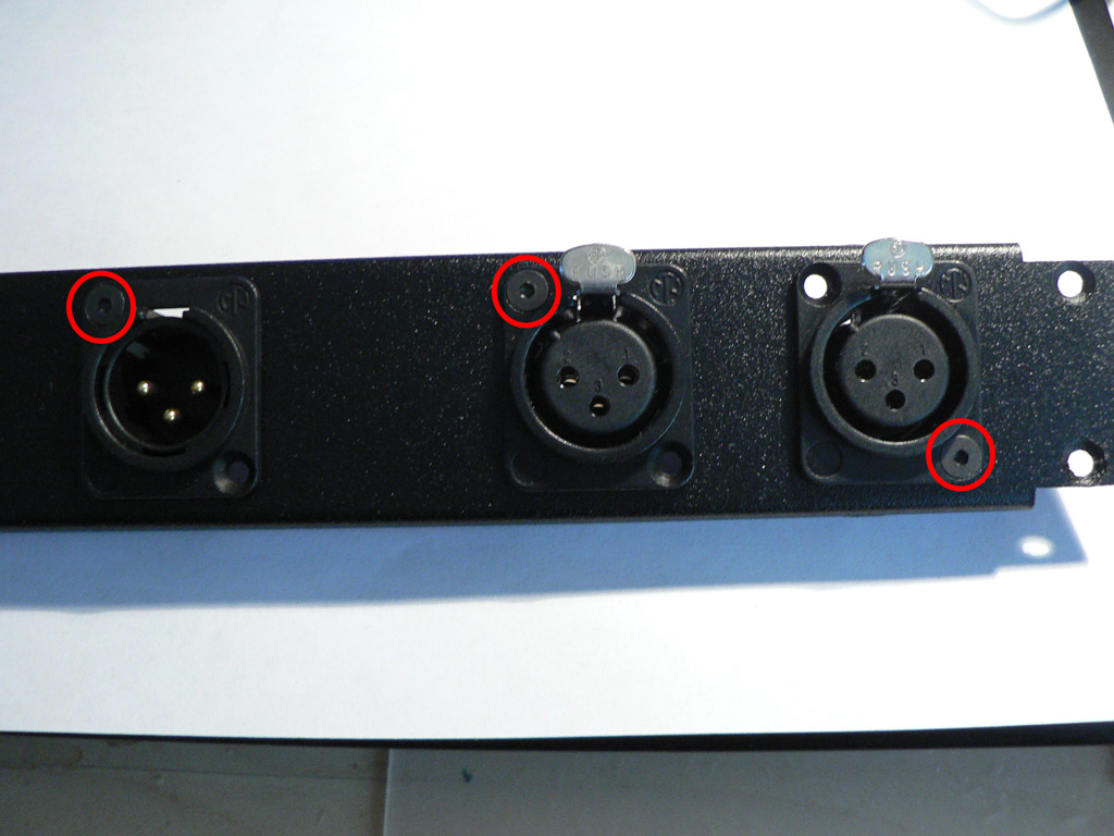
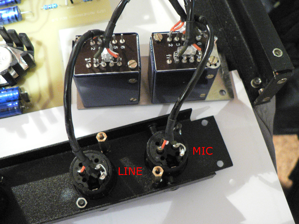
Screw the input and output XLRs to the back panel - 1 screw per connector as shown on the photo. |
 |
|
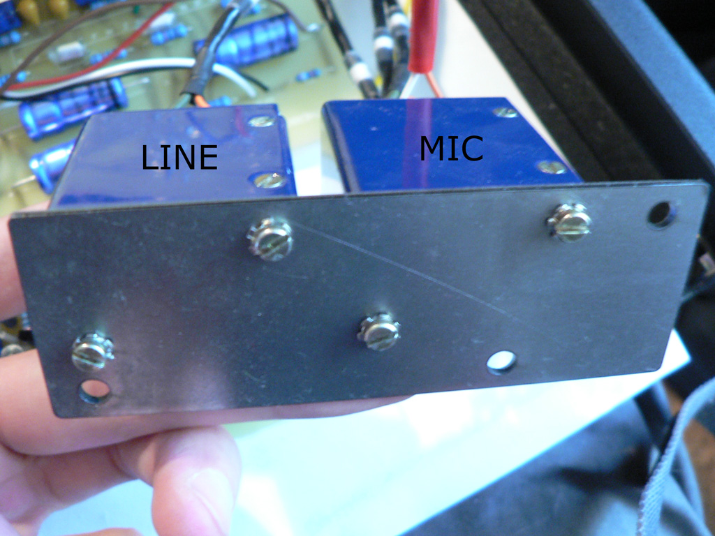
Take the 1073 input transformers mounting bracket and screw input transformers to it as shown on the photo. Note the lock washers - we suggest using lock washers in all places because they prevent screws from loosing over time or from moving the unit around. |
 |
|
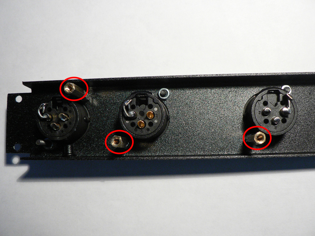
Fix XLRs with second screws. Use 25mm stand-offs instead of nuts (circled in red on the photo).
Solder XLRs chassis conductor with respective pins 1. Use heavy gauge wire for this (we used the wires of some power diodes for this). It is common practice to wire cable shields directly to chassis to avoid noise coupling into the signal ground.
While you have not made any solder connections yet make sure that you have good contact between each connector chassis/pin 1 bond and the back panel itself. Use your DMM to measure resistance between the XLRs pin 1 and any exposed metal of the panel (it is convenient to use the inside part of threaded inserts for that). If your DMM shows the resistance of 0.5 ohm or more you need to scrub the paint from the inside edge of all three holes that hold this XLR (one mounting hole and two fixing holes). Scrubbing off the paint under the screws will also help (the same procedure that we did during the very first step for the IEC receptacle).
It is very important to get good contact to chassis if you want your unit to perform up to its noise specs. |
 |
|
Install the IEC receptacle. Solder a short thick wire to the earth terminal. Opposite end of this wire should be connected to the chassis bolt (the one which have the paint around the hole removed). We used a crimp lug for this, but you can strip the wire, form a ring and tin it instead.
Make sure that this connection is very reliable. Install lock washers to prevent the screw loosing over time.
IF THIS CONNECTION FAILS THE UNIT MAY POSE POTENTIAL THREAT TO THE HEALTH AND LIVES OF OPERATORS! |
 |
|
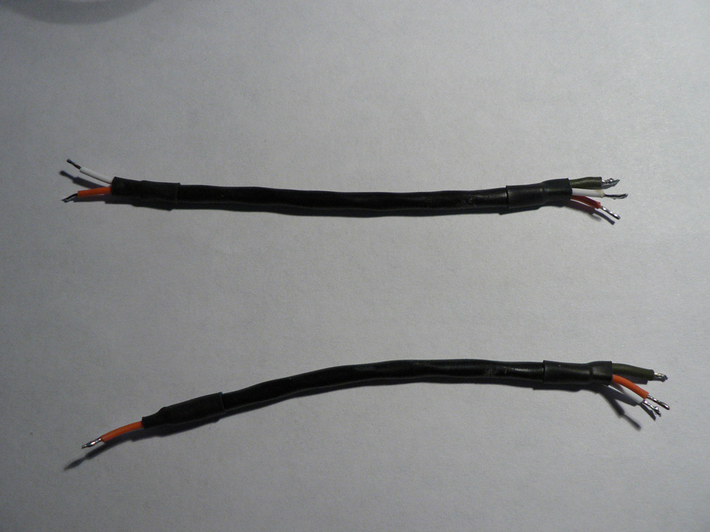
Prepare two 10 cm (5") pieces of wire. The shield should be exposed at one side of the wire only. |
 |
|
Solder these wires to input transformers and input XLR connectors. The shield of each wire should be soldered to the corresponding pin 1 of the XLR. Connect each "hot" wire to the pin 2 of the corresponding transformer, connect each "cold" wire to the pin 5 of each corresponding transformer. |
 |
|
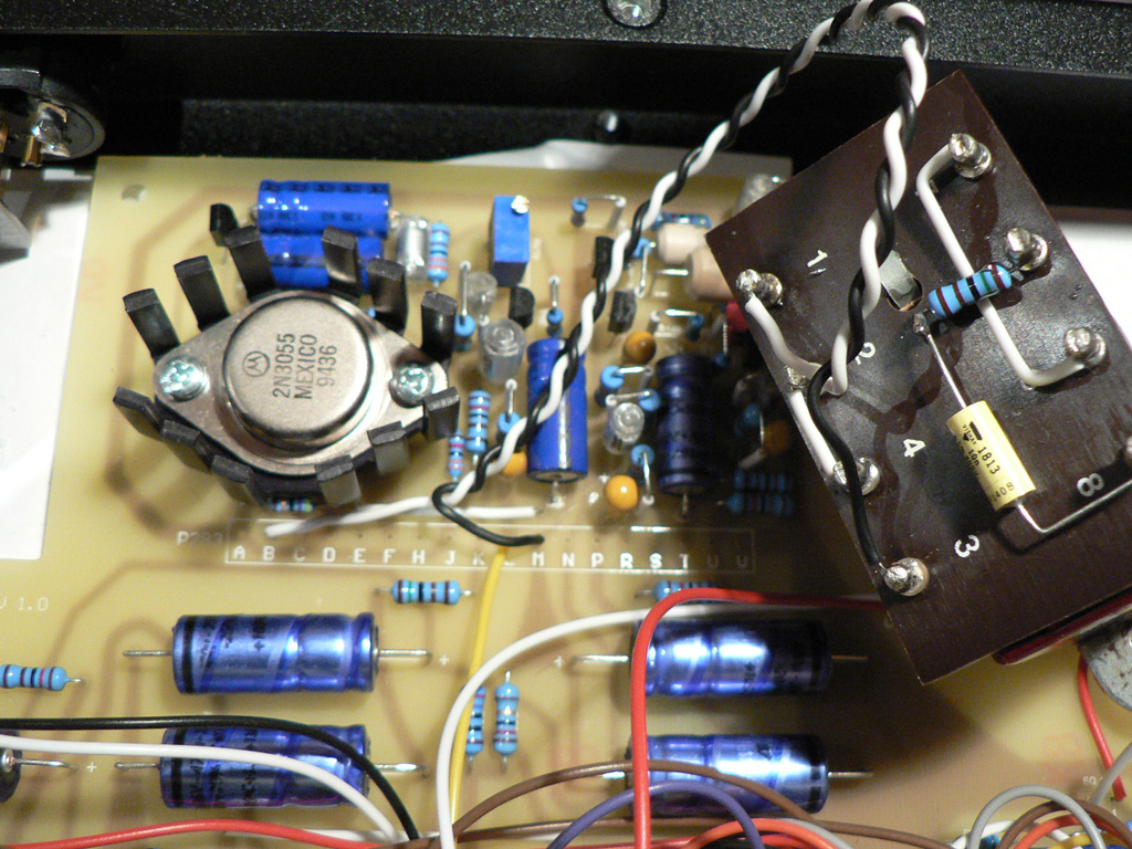
Prepare a twisted pair of wires and connect terminal B of P283 to pin 1 of output transformer, and terminal M of P283 to pin 3 of output transformer. |
 |
|
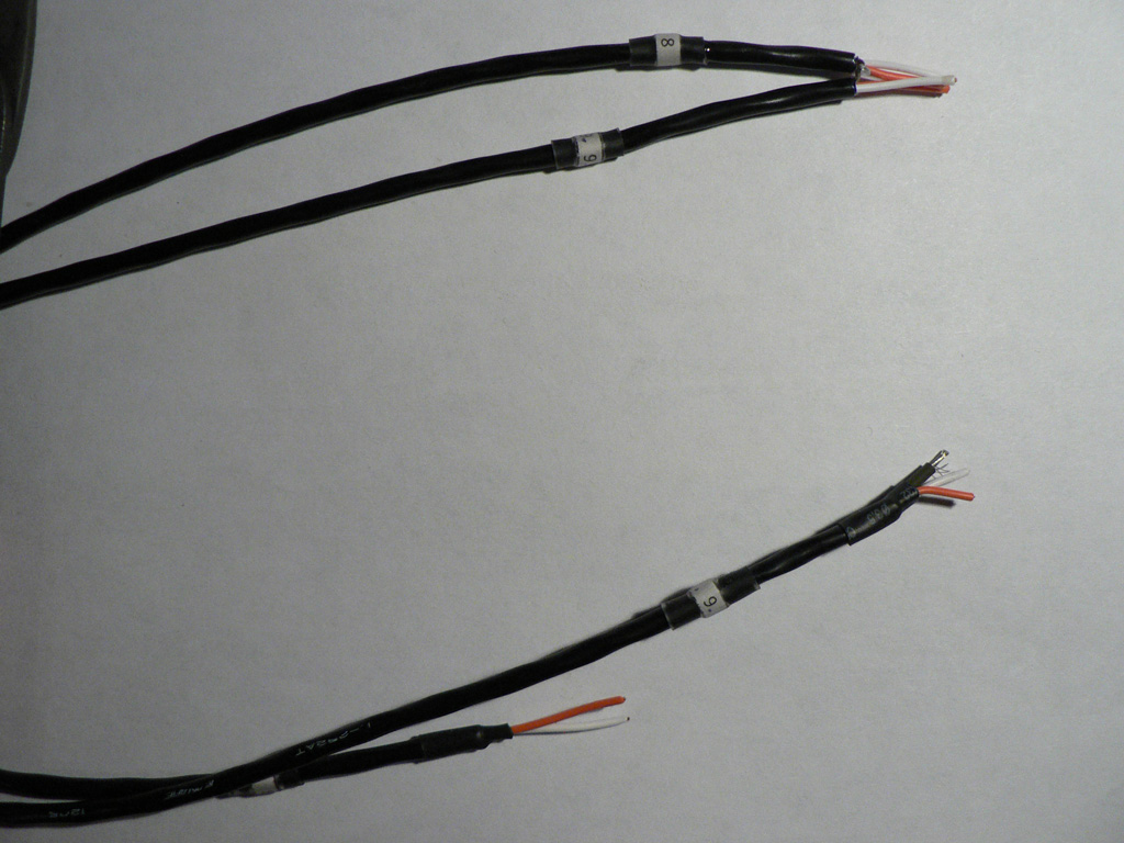
Prepare two wires marked "8" and "9". Length of wire "8" is 36 cm (15"), length of wire "9" is 46 cm (18"). Wire "8" is used for connecting output transformer to the "Phase" switch. Wire "9" connects "Phase" switch with output XLR.
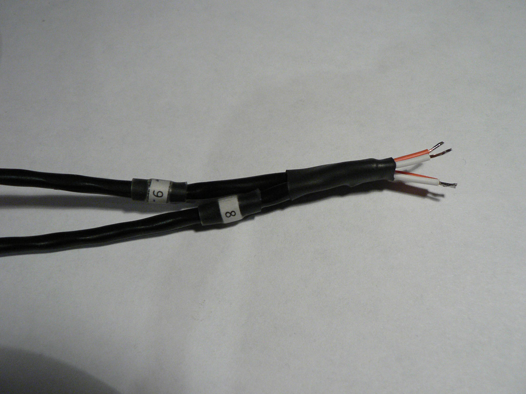
Solder shields together at one side. The opposite end of wire "9" should have shield exposed. The opposite end of wire "8" should have only "hot" and "cold" wires exposed. |
 |
|
Put the heatshrink tubing around the shields joint. |
 |
|
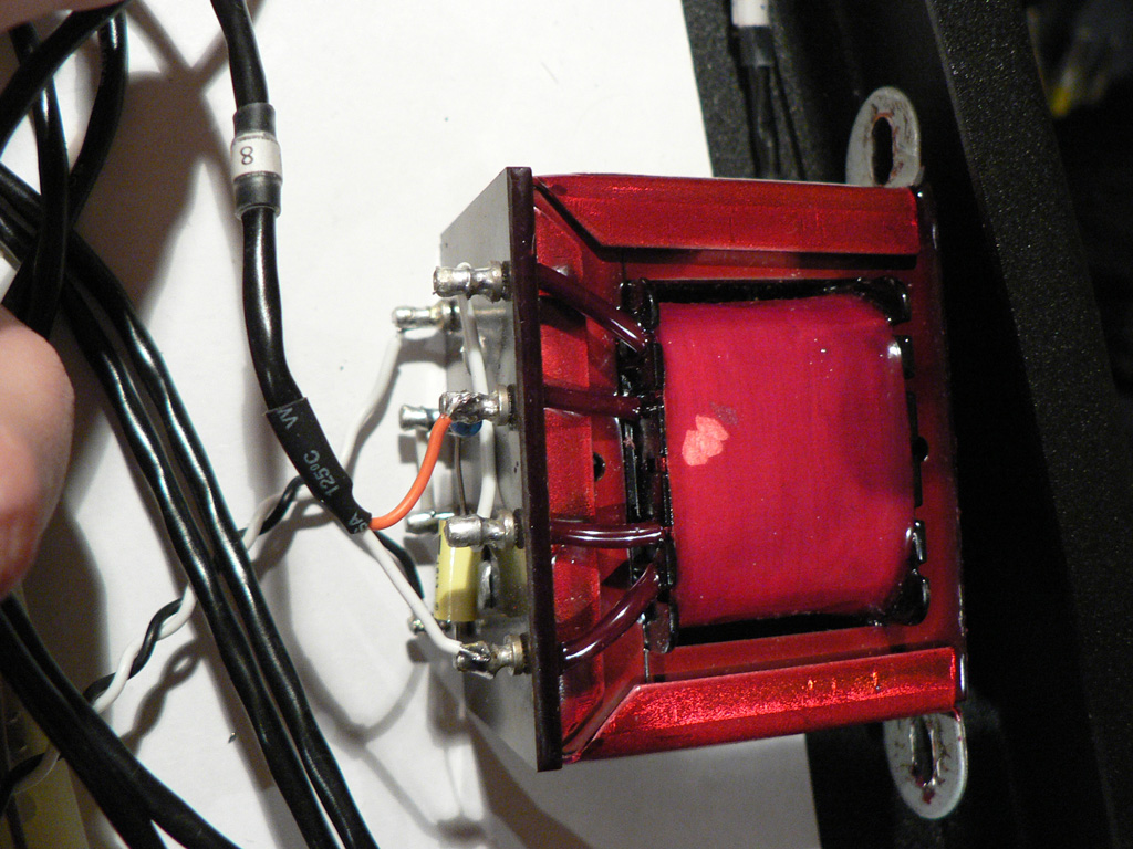
Solder the free end of the wire "8" to the output transformer. "Hot" wire connects to pin 5 of the transformer, "cold" wire - to pin 8 of the transformer. |
 |
|
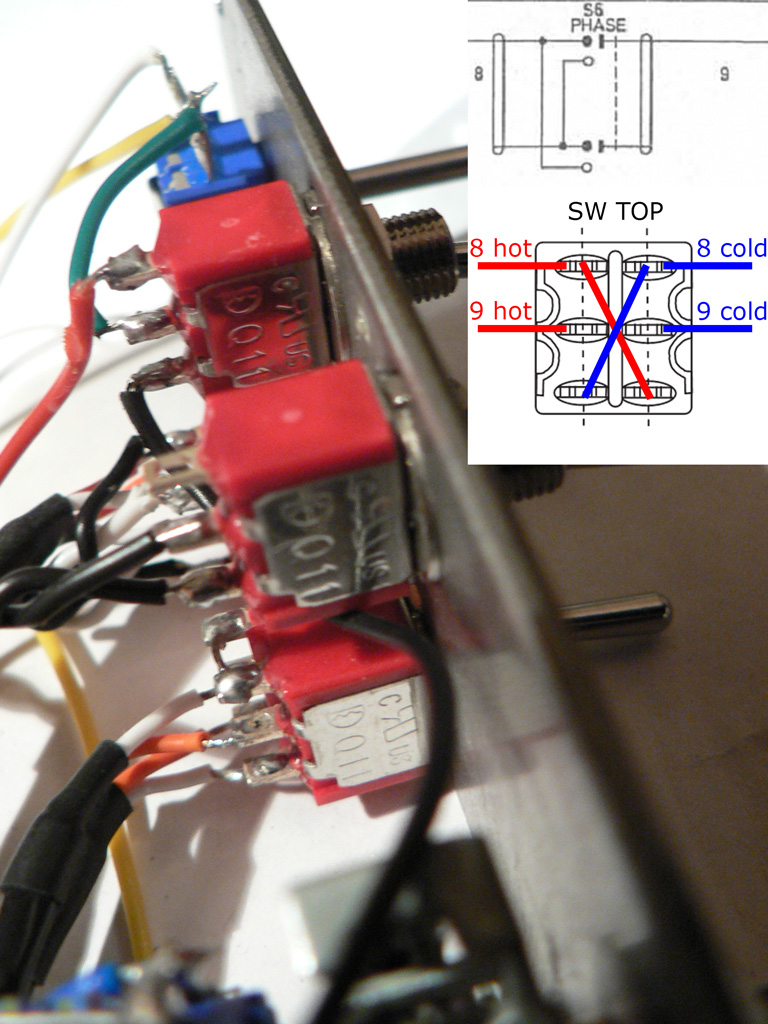
Take the end of the wire with shields soldered together. Connect the wire "9" to the common terminals of the "Phase" switch, connect the wire "8" to the upper terminals of the the switch (the ones that are connected to the common terminals when the switch lever is down). Use two short twisted wires to connect top terminals of the switch to bottom ones in reverse. Refer to the picture and schematic on the photo if in doubt.
Solder wire "9" to the output XLR. |
 |
We can now move on to the PSU wiring.