This is for old revision boards (before rev. 2).
|
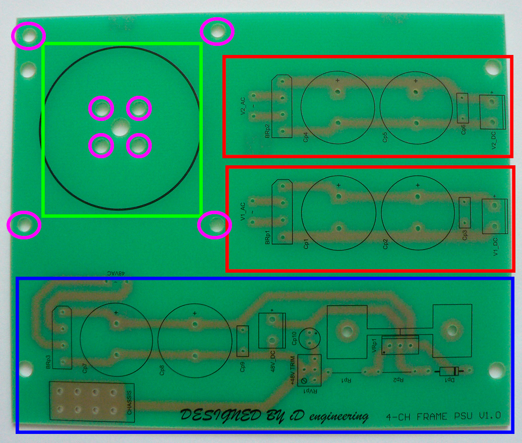
Areas marked with red denote unregulated power rails. Depending on the modules, you may need one or two rails of unregulated power. Blue recangle marks the phantom power section. Please note that this section has its own separate ground. This ground should be tied to chassis for the phantom power to work correctly. Use any of the CHASSIS pads to connect phantom ground to chassis star ground point. Green rectangle marks a power transformer. Secondary windings of the transformer depend on the modules. Keep in mind, that there's no voltage multiplier in this version of the PSU, so you'll need a 44V winding to get the phantom working. There are three options for mounting the power transformer:
Please note: grounding of unregulated power rails is taken care of at the modules. Ground these rails only if this is explicitly stated in the modules building Guide. |
 |
|
Testing procedure:
|